Axial eddy current damper based on spiral transmission method

An eddy current damper and eddy current damping technology, applied in the direction of spring/shock absorber, vibration suppression adjustment, spring, etc., can solve the problems of difficulty in making large damping coefficient and low working frequency, and achieve simple structure, low cost, The effect of improved control efficiency

Active Publication Date: 2014-05-28
湖南省潇振工程科技有限公司
View PDF7 Cites 48 Cited by
  • Summary
  • Abstract
  • Description
  • Claims
  • Application Information

AI Technical Summary

Problems solved by technology

[0003] The object of the present invention is to provide an axial eddy current damper based on a screw transmission method, which can damp the rotary eddy current Part of the damping coefficient is amplified by hundreds or thousands of times, and transformed into a very large axial damping coefficient, which solves the problem that it is difficult to manufacture axial dampers with large damping coefficients in the general eddy current method, and is especially suitable for applications with low operating frequency and high requirements. Vibration control of large civil engineering structures with damping coefficient, simple and durable structure

Method used


Image

  • Axial eddy current damper based on spiral transmission method
  • Axial eddy current damper based on spiral transmission method
  • Axial eddy current damper based on spiral transmission method

Examples


Embodiment 1

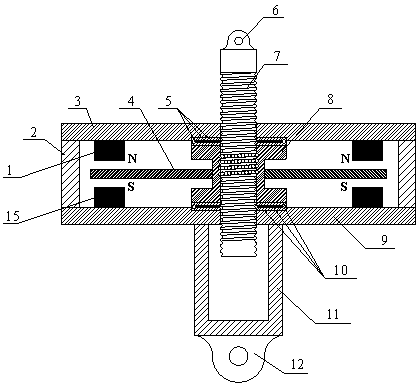
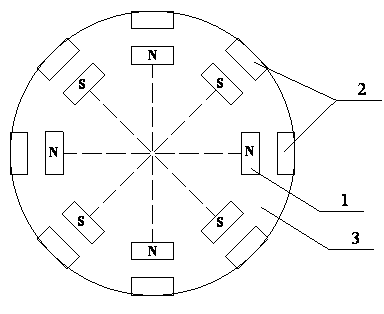
[0032] Such as figure 1As shown, an axial eddy current damper based on a screw transmission method includes a screw auxiliary transmission assembly and a rotary eddy current damping generator. The upper disk 3 and the lower disk 9 are made of magnetically permeable material, and the helical auxiliary transmission assembly runs through the upper disk 3 and the lower disk 9 along the axial direction of the upper disk 3 and the lower disk 9, and on the upper Between the disc 3 and the lower disc 9, there is a rotating disc 4 made of conductive material parallel to the upper disc 3. The rotating disc 4 is installed on the helical auxiliary transmission assembly and is made with the helical auxiliary transmission assembly. Rotational movement; 8 pairs of magnets are also arranged between the upper disk 3 and the lower disk 9, each pair of magnets includes an upper magnet 1 and a lower magnet 15 installed below the upper magnet 1 along the axial direction of the upper disk 3, so In...

Embodiment 2

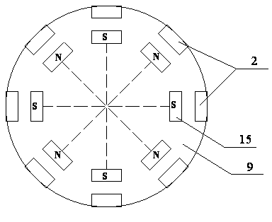
[0037] Such as Figure 4 As shown, an axial eddy current damper based on a screw transmission method includes a screw auxiliary transmission assembly and a rotary eddy current damping generator. The upper disk 3 and the lower disk 9 are made of magnetically permeable material, and the helical auxiliary transmission assembly runs through the upper disk 3 and the lower disk 9 along the axial direction of the upper disk 3 and the lower disk 9, and on the upper Between the disc 3 and the lower disc 9, there is a rotating disc 4 made of magnetically permeable material parallel to the upper disc 3. The rotating disc 4 is installed on the helical auxiliary transmission assembly and moves with the helical auxiliary transmission assembly. Rotating motion; 8 pairs of magnets are also arranged between the upper disk 3 and the lower disk 9, each pair of magnets includes an upper magnet 1 and a lower magnet 15 installed below the upper magnet 1 along the axial direction of the upper disk 3...


PUM


Abstract

The invention relates to a large axial eddy current damper manufactured through a spiral transmission method. The axial eddy current damper based on the spiral transmission method comprises a spiral pair transmission assembly and a rotary eddy current damping generator. The rotary eddy current damping generator comprises an upper disc and a lower disc which are consistent in size, are vertically parallel and are made of magneto-conductive materials, wherein a rotary disc which is parallel with the upper disc and is made of electricity-conductive materials or magneto-conductive materials is arranged between the upper disc and the lower disc, the rotary disc is installed on the spiral pair transmission assembly and rotates along with the spiral pair transmission assembly, a plurality of pairs of magnets are further arranged between the upper disc and the lower disc, and the opposite magnetic poles of an upper magnet and a lower magnet of each pair of magnets are opposite in polarity. According to the axial eddy current damper based on the spiral transmission method, axial movement of a controlled structure is converted into the rotary movement of an inner structure of the damper to be controlled through a spiral pair, the control efficiency is largely improved, and the ratio between the damping force of the axial eddy current damper and the self weight is improved to the level equal to that of a viscous fluid damper or higher level.

Description

technical field [0001] The invention relates to a large-scale axial eddy current damper made by means of screw transmission, which is especially suitable for passive and semi-active vibration control of large-scale civil engineering structures with low operating frequency, large damping coefficient and long working stroke. Background technique [0002] The basic principle of eddy current damping is: when the conductor plate in the magnetic field cuts the magnetic force line, an eddy current will be generated in the conductor plate, and the eddy current will generate a new magnetic field opposite to the direction of the original magnetic field, thereby forming a new magnetic field between the original magnetic field and the conductor. The damping force hinders the relative movement of the two, and the resistance effect of the conductor plate converts the kinetic energy of the conductor plate into heat energy and dissipates it through eddy currents. If the conductor plate is ...

Claims


Application Information

Patent Timeline
Patent Type & Authority Applications(China)
IPC IPC(8): F16F6/00
CPCF16F15/035
Inventor 陈政清黄智文王建辉华旭刚
Owner 湖南省潇振工程科技有限公司
Why Eureka
Try Eureka