Cascading valve clack type adjusting valve

A technology of regulating valve and valve disc, which is applied in valve details, lift valve, parts contacting between valve elements and valve seat, etc. The effect of improving the sealing level of the valve

Inactive Publication Date: 2014-05-28
HARBIN HBC VALVE
5 Cites 2 Cited by

AI-Extracted Technical Summary

Problems solved by technology

In order to improve the sealing level, some control valves use unbalanced dis...

Abstract

The invention relates to a cascading valve clack type adjusting valve, and belongs to the field of thermal power and nuclear power valves. The cascading valve clack type adjusting valve is arranged on a water vapor system pipeline of a thermal power and nuclear power unit and is important equipment for adjusting flow, pressure and temperature of media. The cascading valve clack type adjusting valve is composed of a valve clack, a spring, an auxiliary valve clack, a valve rod, a valve clack pressing cover and the like, and the auxiliary valve clack and the valve rod are of an integral structure. When the valve is opened, the auxiliary valve clack is firstly opened, an upper cavity and a lower cavity of the valve clack are communicated, the valve clack is changed to be of a balance structure, and the valve rod drives the valve clack to move vertically through the valve clack pressing cover and the spring. When the valve is closed, the valve rod compresses the spring, the auxiliary valve clack compresses the inner sealing face of the valve clack, the sealing face on the lower portion of the valve clack compresses the sealing face of a valve seat, the two sealing faces are sealed, and the valve clack is changed to be of an unbalance structure. Opening force of the valve is effectively reduced, and sealing performance in the valve closing process is improved.

Application Domain

Pressure relieving devices on sealing facesSlide valve +2

Technology Topic

Water vaporVALVE PORT +1

Image

  • Cascading valve clack type adjusting valve

Examples

  • Experimental program(1)

Example Embodiment

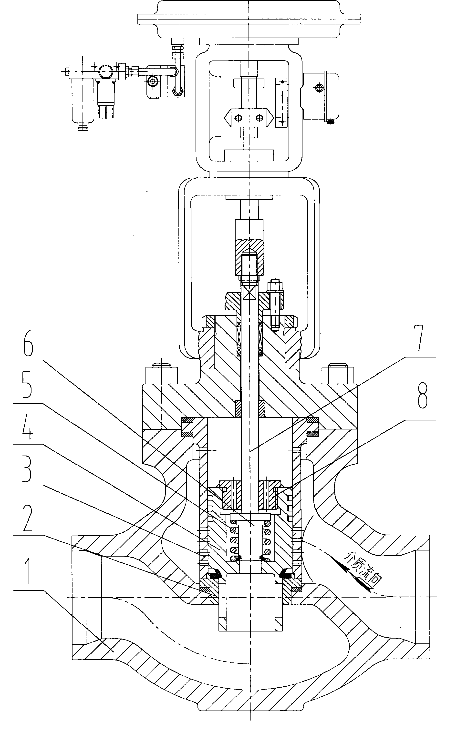
[0013] In the embodiment shown in the figure, the center of the valve disc 4 is drilled with an inner flow channel hole, and the upper part is processed with a sealing surface. The valve stem 7 and the auxiliary valve disc 6 are an integrated structure, and the valve disc 4 and spring 5 pass through the valve disc gland 8 Connect with the valve stem 7. When the valve is closed, the valve stem 7 compresses the spring 5, the auxiliary disc 6 presses against the inner sealing surface of the disc 4, and the lower sealing surface of the disc 4 presses against the sealing surface of the valve seat 2 to achieve two sealing surfaces sealing, and the disc 4 becomes non- Balance structure; when the valve is opened, the auxiliary valve flap 6 is opened first, the upper and lower chambers of the valve flap 4 are connected, and the valve flap 4 becomes a balanced structure. The valve stem 7 drives the valve flap 4 up and down through the valve flap 8 and the spring 5.

PUM

no PUM

Description & Claims & Application Information

We can also present the details of the Description, Claims and Application information to help users get a comprehensive understanding of the technical details of the patent, such as background art, summary of invention, brief description of drawings, description of embodiments, and other original content. On the other hand, users can also determine the specific scope of protection of the technology through the list of claims; as well as understand the changes in the life cycle of the technology with the presentation of the patent timeline. Login to view more.
Why Eureka
Try Eureka