Follow-up backflow preventer

A backflow preventer and follow-up technology, applied in the direction of functional valve types, engine components, pipe components, etc., can solve the problems of large resistance, reduce spring elastic resistance, fail to eliminate spring elastic resistance, etc., achieve constant performance and reduce resistance Effect

Inactive Publication Date: 2014-05-28
何际跃
View PDF7 Cites 0 Cited by
  • Summary
  • Abstract
  • Description
  • Claims
  • Application Information

AI Technical Summary

Problems solved by technology

The disadvantage of the existing backflow preventer is that it has high resistance and high energy consumption, which is mainly caused by the spring structure that establishes the stepped pressure difference. flow loss, and the elastic resistance increases with the increase of the flow rate. It can be seen from the process of its technological development that the standard implemented by the backflow preventer has developed from the urban construction industry standard (CJ / T160-2002) to the urban construction product industry standard (CJ / T160-2002) / T160-2010), to the national standard (GB / T25178-2010), and the recent mechanical industry standard (JB / T11151-2011), the purpose of which is not to improve safety performance, but to try to reduce head loss, but Due to the inheritance of the traditional spring structure, the drag reduction method basically relies on reducing the safety parameters, failing to eliminate the elastic resistance of the spring, allowing the head loss to remain at a high level above 0.06Mpa, the effect is not ideal, and the development process has also proved that in the existing It is difficult to improve and break through on the basis of technical ideas, and high resistance and high energy consumption have become the biggest defect of existing technologies

Method used


Image

  • Follow-up backflow preventer
  • Follow-up backflow preventer
  • Follow-up backflow preventer

Examples


Embodiment Construction

[0026] The present invention will be further described below in conjunction with the accompanying drawings.

[0027] 1. Workflow

[0028] The working process of the present invention is divided into circulation working condition, closed working condition, low water pressure working condition, drainage working condition and reset working condition, which are described as follows:

[0029] 1. Circulation conditions

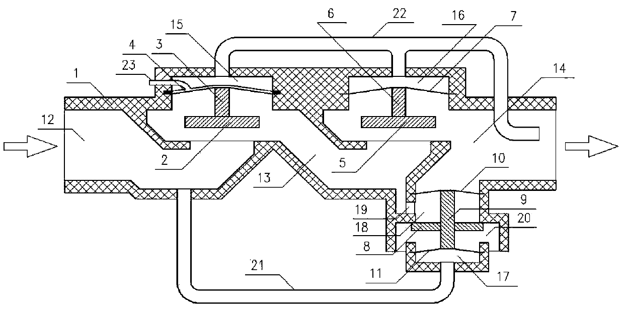
[0030] Such as figure 1 Shown: When the water pressure in the water inlet chamber 12 is higher than the set value, that is, when the water pressure is turned on, the force of the water is greater than the gravity of the gravity check valve 1 2 and the gravity check valve 2 5, and the gravity check valve 1 2 The gravity check valve 2 and 5 are fully opened successively, so that water can flow through the water inlet chamber 12, the valve chamber 13 to the water outlet chamber 14 smoothly. When water flows, on the flow process from the water inlet chamber 12 to the...


PUM


Abstract

The invention discloses a follow-up backflow preventer which is a place used for strictly allowing pressure water in a pipeline to unidirectionally flow. The follow-up backflow preventer is mainly composed of a valve body (1), a gravity-type check valve I (2), a gravity-type check valve II (5) and a pressure difference drain valve (8), and the valve body (1) is mainly composed of a water incoming cavity (12), a valve cavity (13), a water outgoing cavity (14), a back pressure cavity I (15), a back pressure cavity II (16), a positive pressure cavity (17), a drain valve cavity (18) and a dewatering cavity (20). Compared with the prior art, the follow-up backflow preventer has the advantages that water flow resistance is greatly reduced, and waterhead loss is allowed to be lowered below 0.015Mpa from 0.1Mpa.

Description

technical field [0001] The invention relates to a backflow preventer, in particular to a low-resistance follow-up backflow preventer used in strictly limited places where pressure water in pipelines can only flow in one direction. Background technique [0002] Backflow preventers are widely used in municipal water supply pipe networks to prevent backflow water generated by users from entering the pipe network again, avoid pollution accidents, and ensure hygienic and safe water supply. According to the requirements of the specification, backflow preventers should be installed at the municipal pipe network and user access points, different systems and diversion points of different water quality, but the allowable head loss of the backflow preventer is generally above 0.05MPa or even 0.1MPa, which significantly increases the municipal The water supply and power consumption of the pipe network and the water leakage rate of the pipe network have caused a lot of waste. For the co...

Claims


Application Information

Patent Timeline
Patent Type & Authority Applications(China)
IPC IPC(8): F16K15/00F16L55/00
CPCF16K11/105F16K17/12
Inventor 何际跃零桂萍
Owner 何际跃
Why Eureka
Try Eureka