Slag discharging device capable of preventing slag discharging amount from being not controlled by slag cooler

A technology of slag cooling machine and slag volume, which is applied to the direction of burning fuel in molten state, lighting and heating equipment, fluidized bed combustion equipment, etc., and can solve the problems of not being controlled by the slag cooling machine and unable to solve the problem of slag volume

Active Publication Date: 2014-05-28
CRYSTAL WATER & BLUE SKY ENVIRONMENTAL ENG
View PDF7 Cites 2 Cited by
  • Summary
  • Abstract
  • Description
  • Claims
  • Application Information

AI Technical Summary

Problems solved by technology

This solution solves the problem of boiler high-temperature ash spraying outside, but it cannot solve the problem that the amount of slag is not controlled by the slag cooler

Method used


Image

  • Slag discharging device capable of preventing slag discharging amount from being not controlled by slag cooler
  • Slag discharging device capable of preventing slag discharging amount from being not controlled by slag cooler
  • Slag discharging device capable of preventing slag discharging amount from being not controlled by slag cooler

Examples


Embodiment 1

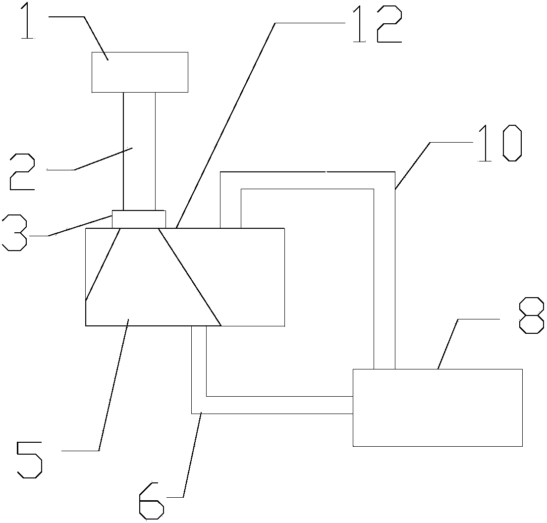
[0034] Such as figure 1 As shown, a slag lowering device that prevents the amount of slag lowering from being controlled by the slag cooler includes an upper section 2 of the slag lowering pipe whose upper end is connected to the slag lowering port 1 of the boiler; The bottom of the buffer bin 12 is also connected with the lower section 6 of the lower slag pipe, and the opening where the bottom of the buffer bin 12 communicates with the lower section 6 of the lower slag pipe is at the top of the ash discharged from the upper section 2 of the lower slag pipe to block the lower slag The other end of the lower section 6 of the lower slag pipe is connected to the slag cooler 8 when the lower outlet of the upper section 2 of the pipe is within the range of the bottom of the ash; It is connected with the cold slag machine 8.

[0035] The upper section 2 of the lower slag pipe is connected with the buffer bin 12 through the three-dimensional expansion joint 3 . The pressure balance...

Embodiment 2

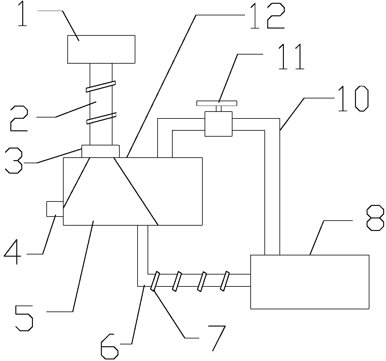
[0042] Such as figure 2As shown, a slag lowering device that prevents the amount of slag lowering from being controlled by the slag cooler includes an upper section 2 of the slag lowering pipe whose upper end is connected to the slag lowering port 1 of the boiler; The bottom of the buffer bin 12 is also connected with the lower section 6 of the lower slag pipe, and the opening where the bottom of the buffer bin 12 communicates with the lower section 6 of the lower slag pipe is at the top of the ash discharged from the upper section 2 of the lower slag pipe to block the lower slag The other end of the lower section 6 of the lower slag pipe is connected to the slag cooler 8 when the lower outlet of the upper section 2 of the pipe is within the range of the bottom of the ash; It is connected with the cold slag machine 8.

[0043] The upper section 2 of the lower slag pipe is connected with the buffer bin 12 through the three-dimensional expansion joint 3 . A valve 11 is arrang...

Embodiment 3

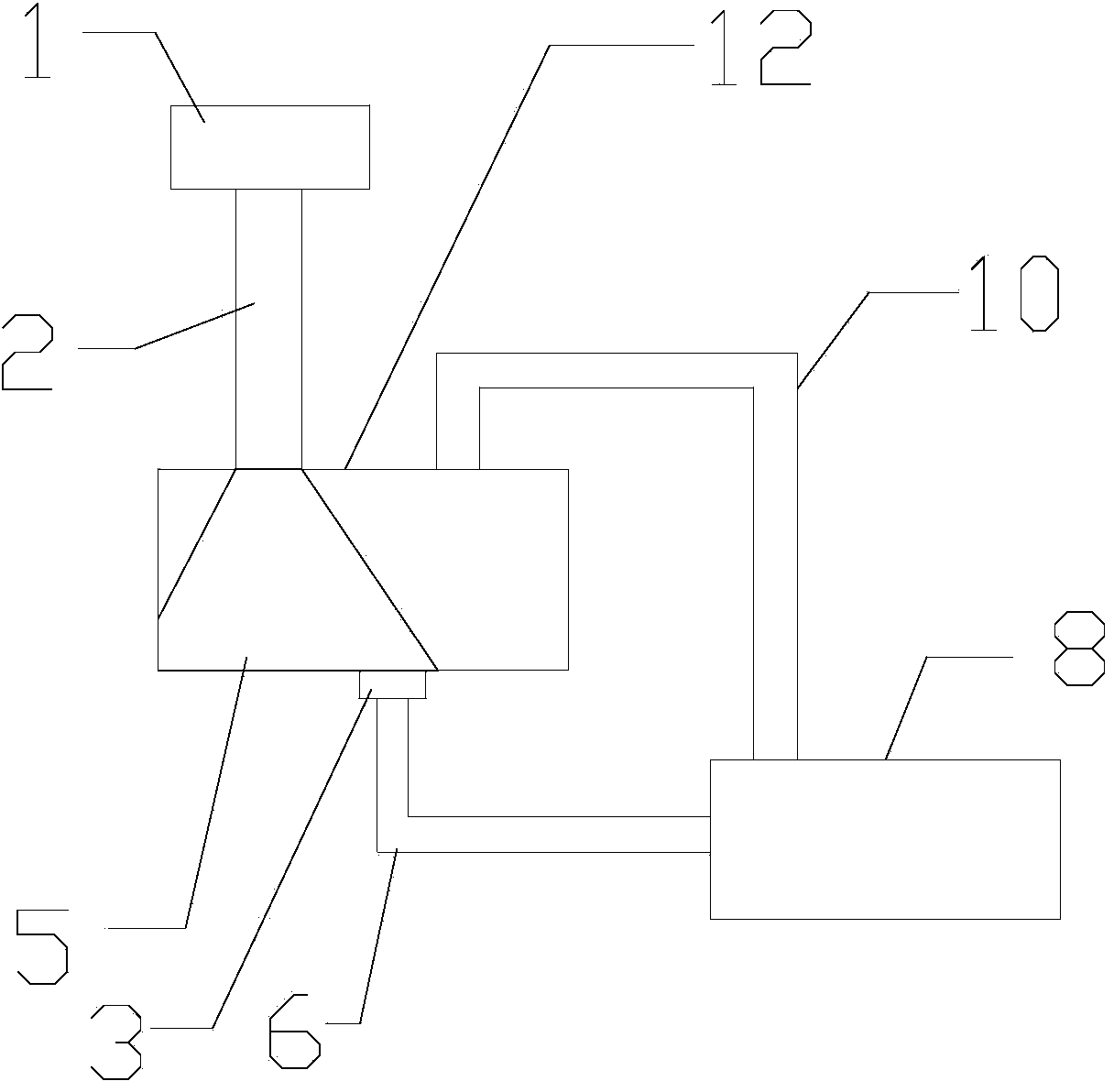
[0051] Such as image 3 As shown, a slag lowering device that prevents the amount of slag lowering from being controlled by the slag cooler includes an upper section 2 of the slag lowering pipe whose upper end is connected to the slag lowering port 1 of the boiler; The bottom of the buffer bin 12 is also connected with the lower section 6 of the lower slag pipe, and the opening where the bottom of the buffer bin 12 communicates with the lower section 6 of the lower slag pipe is at the top of the ash discharged from the upper section 2 of the lower slag pipe to block the lower slag The other end of the lower section 6 of the lower slag pipe is connected to the slag cooler 8 when the lower outlet of the upper section 2 of the pipe is within the range of the bottom of the ash; It is connected with the cold slag machine 8.

[0052] The staggered arrangement of the lower section 6 of the lower slag pipe and the upper section 2 of the lower slag pipe can delay the falling speed of ...


PUM


Abstract

The invention relates to a slag discharging device capable of preventing the slag discharging amount from being not controlled by a slag cooler. The slag discharging device comprises a slag discharging pipe upper section of which the upper end is connected with a boiler slag discharging opening, wherein the lower end of the slag discharging pipe upper section is communicated with a buffering bin; the bottom of the buffering bin is further communicated with a slag discharging pipe lower section; the opening, communicated with the slag discharging pipe lower section, of the bottom of the buffering bin is positioned within the range of ash bottom when the top of the ash discharged from the slag discharging pipe upper section blocks the lower discharging opening of the slag discharging pipe upper section; the other end of the slag discharging pipe lower section is connected with the slag cooler; the buffering bin is further communicated with the slag cooler through a pressure-equalizing pipe used for reducing the pressure inside the buffering bin. The slag discharging device solves the problem that the slag discharging amount of a boiler cannot be controlled, and has extremely high popularization value.

Description

technical field [0001] The invention relates to a boiler slag lowering device, in particular to a slag lowering device which prevents the amount of slag lowering from being controlled by a slag cooler. Background technique [0002] The lower slag pipe of the circulating fluidized bed is located between the boiler and the slag cooler, and is the passage for leading the hot slag from the boiler into the slag cooler. Under normal conditions, the amount of slag discharged by the circulating fluidized bed boiler should be controlled by the speed of the slag cooler, so as to control the stability of the bed pressure of the circulating fluidized bed boiler. The slag in the boiler furnace enters the slag cooling machine through the slag lowering pipe, and forms a slag pile at the nozzle of the slag lowering pipe. When the slag pile blocks the nozzle of the slag lowering pipe, the slag in the furnace will no longer enter the slag cooling machine. When the slag cooler rotates, the sl...

Claims


Application Information

Patent Timeline
Patent Type & Authority Applications(China)
IPC IPC(8): F23C10/24
Inventor 郗厚站
Owner CRYSTAL WATER & BLUE SKY ENVIRONMENTAL ENG
Why Eureka
Try Eureka