Near-to-eye display type optical system based on curved surface microlens array

A microlens array and optical system technology, applied in the field of optical systems, can solve the problems of insufficient volume and weight of optical imaging components, and achieve the effects of increasing light energy utilization, reducing weight and volume, and enhancing image brightness

Inactive Publication Date: 2014-05-28
CHENGDU BEST OPTO ELECTRONICS TECH
View PDF5 Cites 37 Cited by
  • Summary
  • Abstract
  • Description
  • Claims
  • Application Information

AI Technical Summary

Problems solved by technology

[0005] The technical problem to be solved by the present invention is to propose a lightweight and miniaturized near-eye display optical system based on curved surface microlens arrays in view of the shortage of volume and weight of optical imaging components in existing near-eye display systems

Method used


Image

  • Near-to-eye display type optical system based on curved surface microlens array

Examples


Embodiment 1

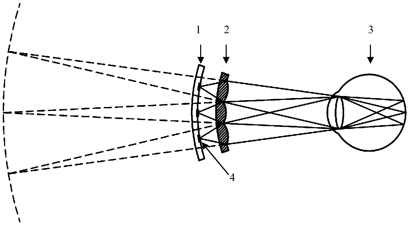
[0023] In this embodiment, the resolution of the OLED display unit is 640×480. Its display units are arranged on a spherical shell with a radius slightly larger than 40mm. The arrangement is square. There are 480 rows in the vertical direction and 640 columns in the horizontal direction. '. The radius of the sphere formed by the pixel surface shall be 40mm. On the spherical shell, the distance between the centers of adjacent pixels is 33um. The schematic diagram of its structure is shown as 1 in FIG. 1 , the viewing angle in the horizontal direction is about 30°, and the viewing angle in the vertical direction is about 22°.

[0024] The radius of the spherical surface where the microlens array is located is 100um smaller than the radius of the spherical surface where the OLED pixel unit is located. The microlens array is located on the outer surface of the spherical surface, and its arrangement period is 33um. The schematic diagram of its structure is shown as 2 in Fig. 1 ....

Embodiment 2

[0027] In this embodiment, the resolution of the OLED display unit is 1920×1080. Its display units are arranged on a spherical shell with a radius slightly greater than 60mm. There are 1080 rows in the vertical direction and 1920 columns in the horizontal direction. The radius of the sphere formed by the pixel surface shall be 60mm. On the spherical shell, the distance between the centers of adjacent pixels is 27.5um. A schematic diagram of its structure is shown as 1 in FIG. 1 . Its viewing angle in the horizontal direction is about 50°, and the viewing angle in the vertical direction is about 28°.

[0028] The radius of the spherical surface where the microlens array is located is 100um smaller than the radius of the spherical surface where the OLED pixel unit is located. The microlens array is located on the outer surface of the spherical surface, and its arrangement period is 27.5um. The schematic diagram of its structure is shown as 2 in Fig. 1 . The microlens array m...


PUM


Abstract

The invention relates to a near-to-eye display type optical system based on a curved surface microlens array, wherein comprises a flexible OLED (organic light emitting diode) display element, and a microlens array manufactured on a curved surface, wherein the curved surface of the OLED and the curved surface of the microlens array are concentric spherical surfaces, the semi-diameter of the curved surface of the OLED is slightly greater, the positions of pixel units of the OLED on the spherical surface are corresponding to the positions of the microlens array one by one, the centers of the OLED and the microlens array are on the same semi-diameter after the assembling. By adopting the microlens array, the weight and the volume of an optical imaging part of the near-to-eye display optical system are obviously decreased, the whole system can be lightened and miniaturized; the microlens array closes to the OLED display unit, so that the light energy utilization rate is increased, the image brightness is increased and the influence of stray light is decreased.

Description

technical field [0001] The invention relates to an optical system, in particular to a near-eye display optical system. Background technique [0002] Wearable devices are an emerging development direction of digital products. They were originally applied to military needs. The basic principle is to enlarge the image on the micro-display through the optical system, so that the viewer's eyes present a large-screen image. Later, it gradually entered the civilian market and has developed rapidly in recent years. Its main application is not only military training, information warfare and flight helmets, but also has a wide range of applications in civilian fields, such as the actual needs of portable computers and personal theater iMax; the development of head-mounted micro-display modules into universally applicable accessories or connectors Plug-ins, used in existing electronic products such as iPods, mobile phones, computers, game consoles, video players, TVs, cameras, etc.; c...

Claims


Application Information

Patent Timeline
Patent Type & Authority Applications(China)
IPC IPC(8): G02B27/01
Inventor 陈晓明邱传凯黄健全蓝鹏
Owner CHENGDU BEST OPTO ELECTRONICS TECH
Why Eureka
Try Eureka