
Directional antenna, directional antenna device and wireless cover system

A directional antenna and wireless technology, applied in the field of directional antenna devices, wireless coverage systems, and directional antennas, can solve the problems of insufficient data capability of wireless coverage systems, large loss of composite material substrates, and low data processing efficiency, and achieve enhanced electromagnetic signal reception. And the effect of transmission ability, good directionality, and meeting the needs of wireless signal processing capabilities

Active Publication Date: 2014-05-28
KUANG CHI INST OF ADVANCED TECH
View PDF5 Cites 0 Cited by
  • Summary
  • Abstract
  • Description
  • Claims
  • Application Information

AI Technical Summary

Problems solved by technology

[0004] Existing directional antennas are mostly made of a combination of vibrators and composite material substrates, and there are problems such as high thickness of the vibrator and large loss of composite material substrates, so that the wireless coverage system using the directional antenna has problems such as low data processing efficiency and limited processing speed. , so there is an urgent need for a directional antenna with good directivity and high throughput to solve the problem of insufficient data capacity in wireless coverage systems

Method used


Image

  • Directional antenna, directional antenna device and wireless cover system
  • Directional antenna, directional antenna device and wireless cover system
  • Directional antenna, directional antenna device and wireless cover system

Examples


Embodiment Construction

[0046] Reference will now be made in detail to the embodiments depicted in the accompanying drawings. In the following detailed description, numerous specific details are set forth in order to provide a thorough understanding of the present invention. However, it will be understood by those skilled in the art that the present invention may be practiced without these specific details. In other embodiments, well-known methods, procedures, components and circuits have not been described in detail so as not to unnecessarily obscure the embodiments.

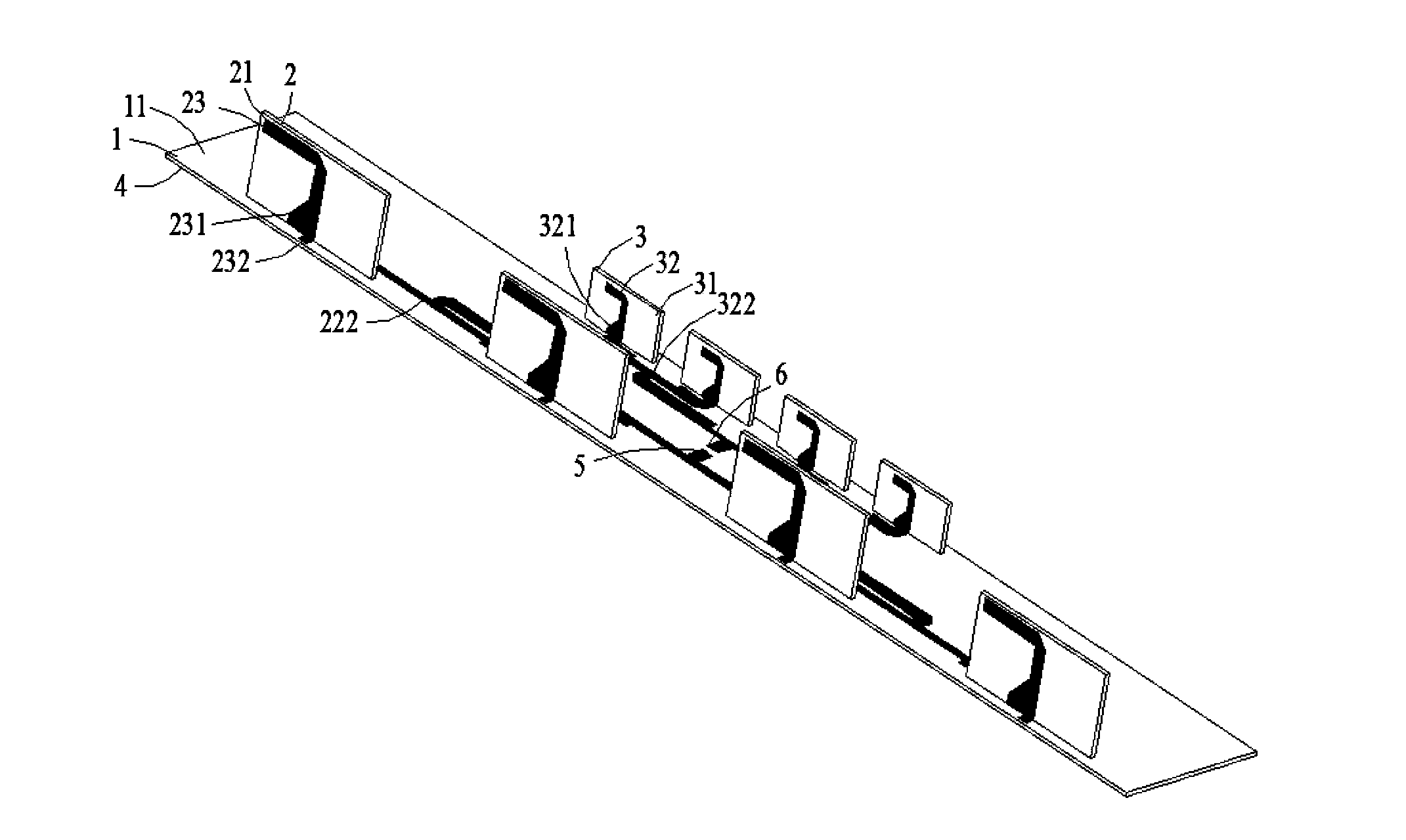
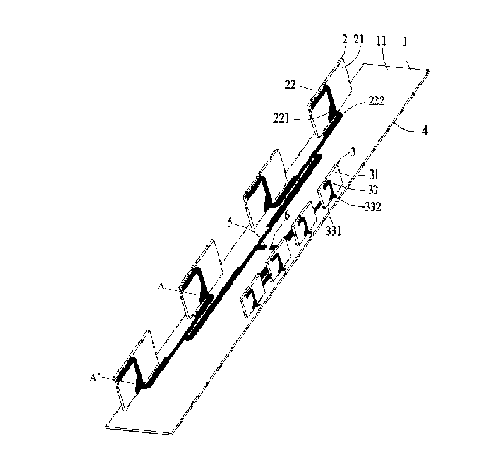
[0047] see figure 1 and figure 2 , which is a schematic diagram of the structure of the directional antenna of the present invention, the directional antenna includes a first substrate 1, a first dipole antenna unit 2, a second dipole antenna unit 3, a metal surface 4, a feeding part 5 and a grounding part 6. The first substrate 1 has a first surface 11 and a second surface (not shown in the figure), using FR4 with a low dielectri...


PUM


Abstract

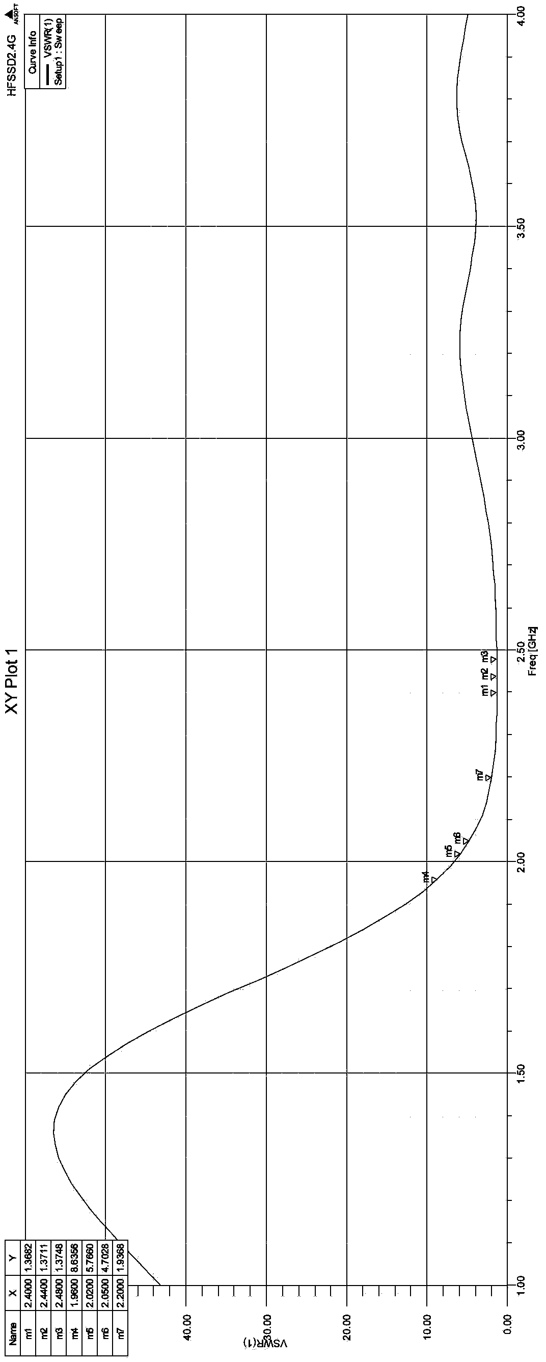
The invention provides a directional antenna comprising a first substrate, wherein the first substrate has a first surface and a second surface; at least one first dipole antenna unit, wherein the first dipole antenna unit is arranged on the first surface and first dipole antenna unit comprises two first dipole units; a metal surface, wherein the metal surface is covered on the second surface, and one end portion of the first dipole unit is in electrical connection with the metal surface; and a feed portion, wherein the feed portion is in electrical connection with the other end portion of the first dipole unit. The directional antenna has the advantages of being good in directivity and good in electromagnetic signal processing capability; meanwhile, gain is high, frequency band is wide and standing-wave ratio is small; magnetic signal reception and sending capability is enhanced; data interaction can be well finished in the wireless cover system; user experience is improved; and the requirements of a conventional wireless cover system for the wireless signal processing capability can be met.

Description

technical field [0001] The invention belongs to the field of communication equipment, and in particular relates to a directional antenna, a directional antenna device and a wireless coverage system. Background technique [0002] With the development of wireless communication technology, more and more mobile communication terminals are put into use, such as mobile phones, PADs, etc., and the data processing capabilities of these mobile terminals have increased significantly. The ability to provide data puts forward higher requirements. [0003] In public places such as museums and exhibition halls, a large number of mobile terminals will be used at the same time to upload videos, pictures, or release messages. There will be a large amount of data transmission demand in a short period of time, which will easily cause network data congestion. As the radiating unit and receiving device of the final radio frequency signal, the directional antenna's working characteristics will d...

Claims


Application Information

Patent Timeline
IPC IPC(8): H01Q1/36H01Q1/50H01Q21/00
Inventor 刘若鹏杨逵
Owner KUANG CHI INST OF ADVANCED TECH
Learn More