Low-cogging-torque flux switching permanent magnet motor

A cogging torque and magnetic flux switching technology, which is applied to the static parts of the magnetic circuit, the rotating parts of the magnetic circuit, the shape/style/structure of the magnetic circuit, etc., can solve the problem of reducing the induced electric potential of the motor, large cogging torque, Increase the difficulty of motor processing and other issues to achieve the effect of saving consumption, reducing cogging torque and simple manufacturing

Inactive Publication Date: 2014-05-28
SOUTHEAST UNIV
View PDF4 Cites 9 Cited by
  • Summary
  • Abstract
  • Description
  • Claims
  • Application Information

AI Technical Summary

Problems solved by technology

Studies have shown that an obvious disadvantage of flux switching permanent magnet motors compared with other permanent magnet motors is that the cogging torque is too large, which is a major factor affecting the torque ripple of the motor
Generally, methods such as rotor virtual slots and rotor flanges are used to reduce the cogging torque of flux switching permanent magnet motors, but this will reduce the induced potential of the motor and increase the processing difficulty of the motor.

Method used


Image

  • Low-cogging-torque flux switching permanent magnet motor
  • Low-cogging-torque flux switching permanent magnet motor
  • Low-cogging-torque flux switching permanent magnet motor

Examples


Embodiment 1

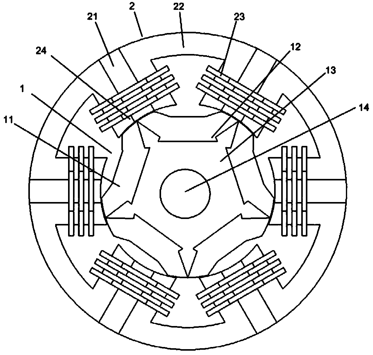
[0019] Embodiment 1: as figure 1 Shown is a cross-sectional view of a 6 / 5 extremely low cogging torque flux switching permanent magnet motor of the present invention. The 6 / 5 extremely low cogging torque flux switching permanent magnet motor includes a stator 2 with a salient pole structure and a rotor 1 with an embedded structure arranged inside the stator. The stator 2 is composed of 6 U-shaped stator cores 22 , 6 parallel permanent magnets 21 and 6 concentrated armature coils 23 . Six U-shaped stator cores 22 are evenly distributed along the circumferential direction of the stator. The stator cores are punched out of silicon steel sheets with a thickness of 0.35 mm to form stator punches, and the punches are laminated axially to form stator cores. The adjacent sides of two adjacent U-shaped stator magnetic cores 22 form a stator tooth, and a parallel permanent magnet 21 is embedded in the two adjacent sides of two adjacent U-shaped stator magnetic cores. A total of 6 para...

Embodiment 2

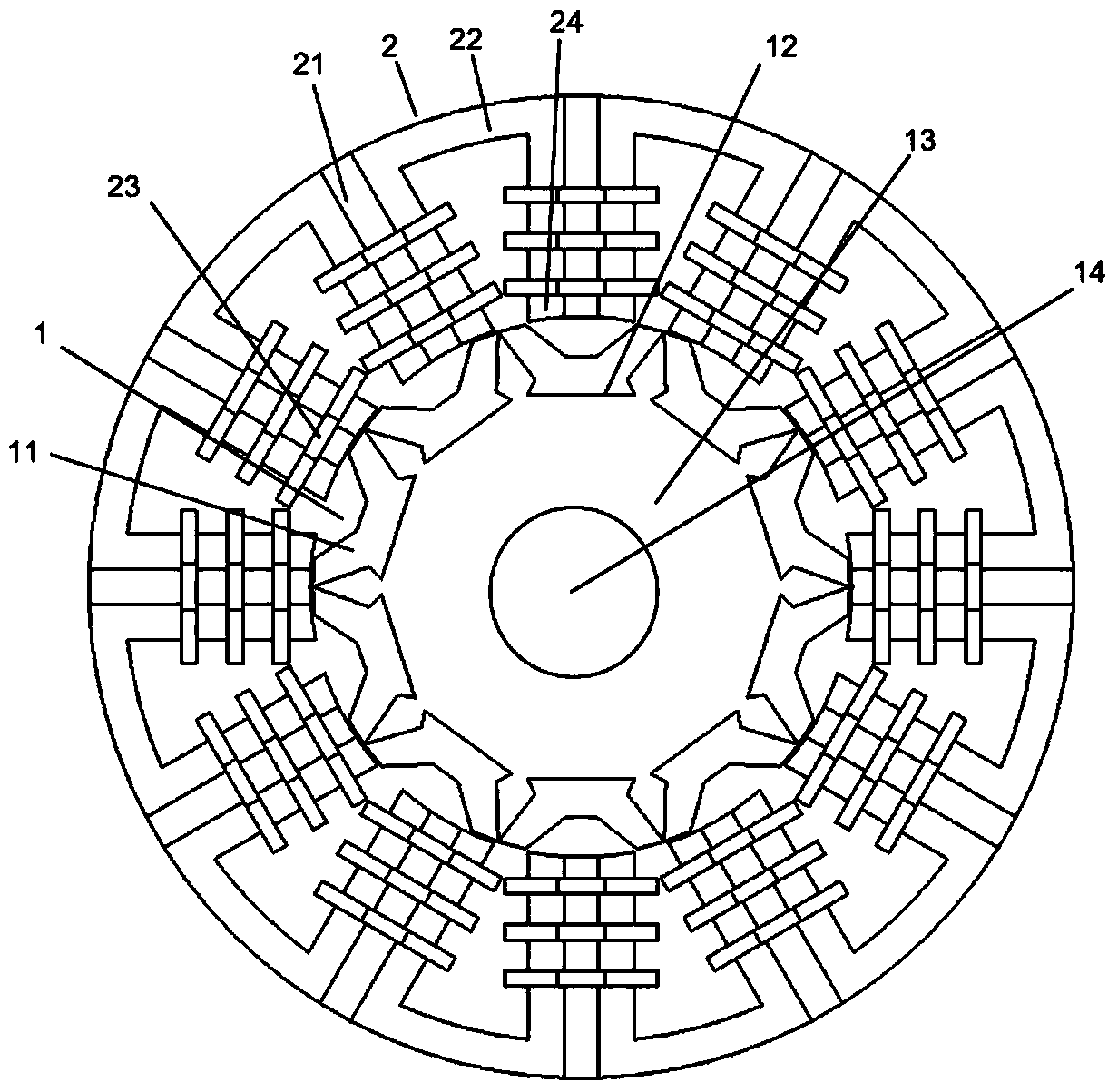
[0020] Embodiment 2: as image 3 Shown is the multiple expansion of the stator unit and the rotor unit of the motor to obtain the sectional view of the 12 / 10 extremely low cogging torque magnetic flux switching permanent magnet motor of the present invention. The motor stator 2 is composed of 12 U-shaped stator cores 22 , 12 parallel permanent magnets 21 and 12 concentrated armature coils 23 . The embedded structure rotor 1 is composed of 10 embedded U-shaped rotor cores 11 , rotor blocks 13 and rotor shafts 14 . The structures of the stator and the rotor are the same as those of the 6 / 5 extremely low cogging torque flux switching permanent magnet motor in Embodiment 1.

[0021] The operation principle of the low cogging torque permanent magnet motor proposed by the present invention is consistent with that of the traditional doubly salient flux switching permanent magnet motor. As the rotor position changes, the amplitude and polarity of the stator flux linkage and induced p...


PUM


Abstract

The invention discloses a low-cogging-torque flux switching permanent magnet motor which comprises a stator of a salient pole structure and a rotor of an embedded structure. The stator is provided with 6n U-shaped stator magnetic-conducting iron cores. Adjacent side edges of every two adjacent U-shaped stator magnetic-conducting iron cores form one stator tooth. A permanent magnet is embedded in each stator tooth. The permanent magnets are magnetized in the tangential direction, and the magnetizing directions of every two adjacent permanent magnets are opposite. The rotor of the embedded structure comprises 5n embedded U-shaped rotor magnetic-conducting iron cores, a rotor block and a rotor shaft, wherein the rotor block and the rotor shaft are made of non-magnetic-conducting materials, the embedded U-shaped rotor magnetic-conducting iron cores are embedded in the rotor block, adjacent side edges of every two adjacent embedded U-shaped rotor magnetic-conducting iron cores form one rotor electrode, and n is a positive integer. The rotor of the embedded structure of the motor has the advantages of being easy to manufacture, solid and durable. The number of used silicon steel sheets is reduced, it is guaranteed that the motor outputs average output torque, and the cogging torque and the torque pulsation of the motor are effectively lowered at the same time.

Description

technical field [0001] The invention relates to a motor, in particular to a torque flux switching permanent magnet motor. Background technique [0002] With global warming, shortage of fossil fuels and environmental pollution, how to use energy more efficiently has become a problem that must be faced in the process of human development. Permanent magnet synchronous motors have the advantages of small size, high power density, high efficiency, high output torque and reliable operation, and have been widely used in many fields, especially in the automotive industry. Permanent magnet synchronous motors are used in new energy played an important role in the development of automobiles. [0003] The flux switching permanent magnet motor belongs to a permanent magnet synchronous motor. Its basic structure is similar to that of a switched reluctance motor, which is a doubly salient pole structure, but with radially magnetized permanent magnets embedded in each stator tooth. The m...

Claims


Application Information

Patent Timeline
Patent Type & Authority Applications(China)
IPC IPC(8): H02K1/14H02K1/17H02K1/22
Inventor 林明耀李念付兴贺郝立
Owner SOUTHEAST UNIV
Why Eureka
Try Eureka