Vacuum cleaner head

A technology of vacuum cleaners and suction pipes, applied in the directions of vacuum cleaners, nozzles, cleaning equipment, etc., can solve problems such as noise, friction, increase, etc.

Inactive Publication Date: 2014-05-28
SEB SA
View PDF11 Cites 8 Cited by
  • Summary
  • Abstract
  • Description
  • Claims
  • Application Information

AI Technical Summary

Problems solved by technology

Conversely, the use of the suction head for water washing makes it unsuitable for use on surfaces that do not tolerate water, such as certain wooden floors or non-washable fiber woven cut pile carpets, and the suction head has no water Use that does not cause effective suction
Finally, this suction head is not conducive to the use of only sucking air, since the lower soleplate is in direct contact with the ground, which causes friction that creates resistance to movement and noise that is not conducive to the comfort of the user
[0004] Finally, document EP1222892B1 discloses a suction head with a slotted bottom plate mounted on a wheel, however air leaks occur between the bottom plate and the ground, making the suction inefficient because the velocity of the air in the grooves is not optimal
In the second implementation, the slotted bottom plate is in direct contact with the ground, but this causes noisy friction and increases the force to be applied to move the suction head
Both compromise the comfort of use and the ergonomics of the equipment offered

Method used


Image

  • Vacuum cleaner head
  • Vacuum cleaner head
  • Vacuum cleaner head

Examples


Embodiment Construction

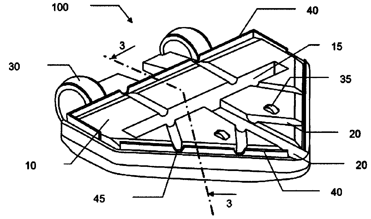
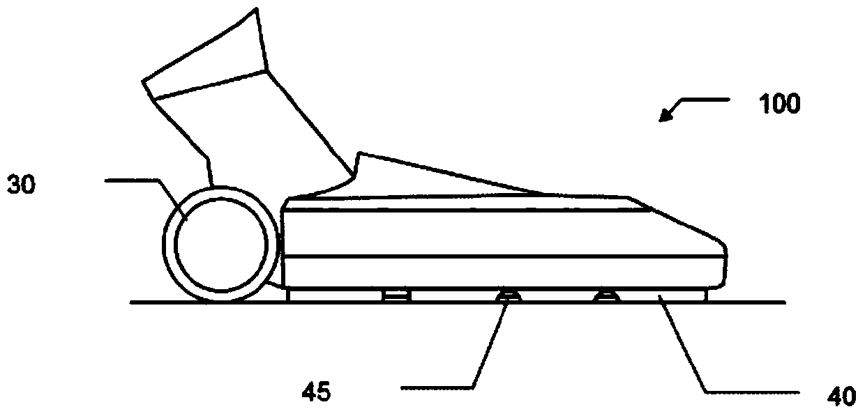
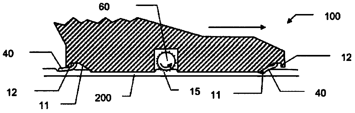
[0020] figure 1 A suction head 100 of a vacuum cleaner according to the invention is shown. The suction head 100 includes a lower base plate 10 with a plurality of suction ducts 20 opening towards the ground. The suction head also comprises wheels 30, 35, the contour of the rolling area of ​​which is barrel-shaped and which define the ground clearance of the base plate 10 when the suction head is placed on a smooth surface. (garde au sol). The tip is generally triangular in shape and at least one of the conduits 20 leads to the tip of the tip. Each duct 20 connects, eg, a slit-shaped suction opening 15 towards the outside of the floor 10, so that the air sucked by the motor of the vacuum cleaner preferably travels in the duct of the floor. In order to have a good suction efficiency, the invention provides, inter alia, that a sealing lip or sealing skirt 40 is provided around the bottom plate. The sealing skirt 40 eliminates the leakage between the smooth ground and the bot...


PUM


Abstract

Vacuum cleaner head (100) comprising a bottom sole (10) and wheels (30, 35) defining the ground clearance of the bottom sole and comprising at least one suction duct (20) open toward the ground and converging from an outer edge of the bottom sole (10) toward a suction orifice (15) connected to the vacuum cleaner, characterized in that the suction head comprises a sealing skirt (40) arranged around the periphery of the bottom sole (10), and in that the sealing skirt (40) has at least one opening (45) positioned opposite said at least one suction duct (20).

Description

technical field [0001] The present invention generally relates to suction heads for vacuum cleaners equipped with skirts. Background technique [0002] Suction heads for vacuum cleaners are known in the prior art, for example as described in document US20050066471A1. The disclosed tip includes a sealing lip that includes a hollowed-out portion that allows air to pass towards the interior of the tip. However, this system especially has the disadvantage that it is not efficient for picking up dirt on the floor, since the velocity of the air in the suction head is not controlled. Furthermore, the suction head is not positioned correctly relative to the ground, since the U-shaped part arranged in the center of the suction head does not prevent the suction head from swiveling, so that the sealing lip cannot evenly ensure the operation of the sealing lip. [0003] Document EP2014212A1 itself has a suction head equipped with a mop for use with a machine for vacuuming and washing ...

Claims


Application Information

Patent Timeline
Patent Type & Authority Applications(China)
IPC IPC(8): A47L9/06
CPCA47L9/0626A47L5/26A47L9/04A47L9/0466
Inventor 赛里·吉诺阿兰·索昂
Owner SEB SA
Why Eureka
Try Eureka