
Glass plate for tempering

A glass plate and glass technology, applied in glass tempering, glass manufacturing equipment, transportation and packaging, etc., can solve the problems of small linear thermal expansion rate, large linear thermal expansion rate, difficult to strengthen, etc., and achieve excellent scratch resistance.

Inactive Publication Date: 2014-05-28
ASAHI GLASS CO LTD
View PDF7 Cites 15 Cited by
  • Summary
  • Abstract
  • Description
  • Claims
  • Application Information

AI Technical Summary

Problems solved by technology

[0006] Regarding the reduction in density of glass, in the case of soda lime silica glass produced by the float process, which is generally used as a glass plate for strengthening, it is about 2.5g / cm at room temperature 3 , moreover, even silica glass is about 2.2g / cm 3 , there is a limit to low density
[0007] On the other hand, regarding the thinning of the thickness of glass, strengthening of glass is known as a technique capable of overcoming a decrease in strength. In thermal strengthening of glass, the temperature difference between the surface and the inside of the glass during cooling is used for strengthening. Therefore, in In the case of thin glass of 2.8 mm or less, it is difficult to strengthen due to temperature difference
As a thermally strengthened glass plate, when the temperature difference between the temperature near the yield point at which thermal strengthening begins and the strain point where the strain freezes is large, or when the coefficient of linear thermal expansion at high temperatures near the yield point is large, strengthening is easy It is preferable to carry on, but this kind of glass has a large linear thermal expansion coefficient from low temperature, so it is not suitable for the case where the linear thermal expansion coefficient at a relatively low temperature is desired to be small according to the application.

Method used


Image

  • Glass plate for tempering
  • Glass plate for tempering

Examples


Embodiment

[0061] Hereinafter, the present invention will be described in more detail by way of examples, but the present invention is not limited to these examples.

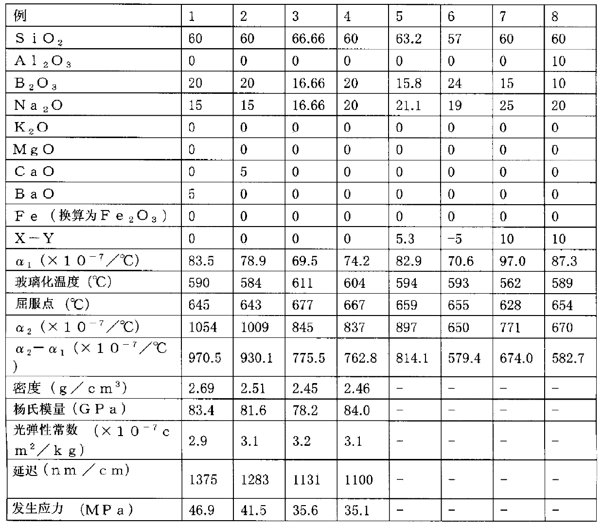
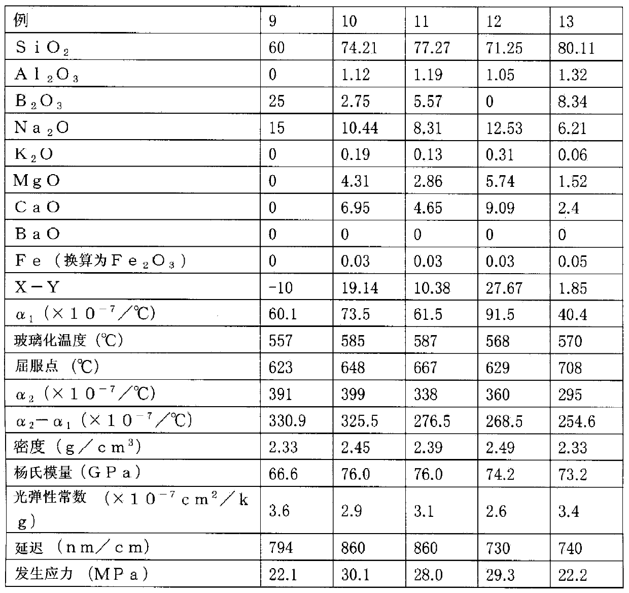
[0062] According to the conditions of the glass composition (Example of the present invention) represented by mol% in Table 1, or the conditions of the glass composition (Comparative Example of the present invention) represented by mol% in Table 2, the oxide, hydroxide Generally used glass raw materials such as substances, carbonates, and nitrates are weighed and mixed under the condition that the glass reaches 500 g. Then, pour the mixture into a platinum crucible, put it into a resistance heating electric furnace at 1450°C, melt it for 1 hour, pour it into a mold, immerse it in a container filled with water for water quenching (Japanese: water castor), and break it into 15mm The following fragments. Next, pour the pieces into a platinum crucible again, melt them for 2 hours, pour them into a mold after defoaming, keep t...


PUM

PropertyMeasurementUnit
glass transition temperatureaaaaaaaaaa

Abstract

Provided is a glass plate for tempering, which is characterized by having a small thermal expansion coefficient under a relatively low temperature, even when the plate is thin, while obtaining a sufficiently high surface compression by the steps involved in conventional thermal tempering. A glass plate for tempering is characterized by having a composition comprising 12.5 to 35 mol% of B2O3; having a composition wherein the difference [X-Y] between the total content X of compound selected from the group consisting of MgO, CaO, BaO, Na2O, and K2O and the total content Y of B2O3 is within a range of -5 to 10 mol%; and being subjected to tempering by heating and quenching.

Description

technical field [0001] The present invention relates to a glass plate for tempering capable of achieving the same or higher strengthening than conventional soda lime glass even when the thickness is thin, and a tempered glass plate obtained by tempering the glass plate. Background technique [0002] Reinforced glass overcomes the technical problem of glass, which is easy to break, and has been used in vehicles and buildings. The tempered glass referred to in the present invention is tempered glass that utilizes heat shrinkage of glass called thermal strengthening or physical strengthening, and refers to windows of vehicles such as passenger cars, trucks, buses, railways, ships, and aircraft. Tempered glass used, tempered glass used for headlights and tail lights, tempered glass used for windows, doors, and showcases of buildings and houses, tempered glass used for furniture such as partition walls, tabletops, bookshelves, and showcases, or office supplies Tempered glass use...

Claims


Application Information

Patent Timeline
Patent Type & Authority Applications(China)
IPC IPC(8): C03C3/089C03B27/012
CPCC03B27/0413C03C3/089C03C3/091Y10T428/315C03B27/04C03C3/087
Inventor 小野圆佳小池章夫安间伸一伊藤节郎
Owner ASAHI GLASS CO LTD
Learn More