Chemically strengthened glass

a technology of chemical strengthening glass and glass, applied in the direction of identification means, instruments, etc., to achieve the effect of high surface compressive stress and high strength

Active Publication Date: 2022-04-26
AGC INC
View PDF28 Cites 5 Cited by
  • Summary
  • Abstract
  • Description
  • Claims
  • Application Information

AI Technical Summary

Benefits of technology

[0013]The chemically strengthened glass of the present invention has a high surface compressive stress and a large depth of a compressive stress layer as compared with those in the conventional art, and also has the total amount of the compressive stresses of a certain value or less and a high strength.

Problems solved by technology

When the chemically strengthened glass drops on the sand or asphalt and is cracked, protruding objects existing on the sand or asphalt stick into the glass, and a position deeper than the glass surface becomes a starting point of cracking.

Method used


Image

  • Chemically strengthened glass
  • Chemically strengthened glass
  • Chemically strengthened glass

Examples


examples

[0136]The present invention is hereunder described by reference to Examples, but it should be construed that the present invention is not limited by these Examples.

[0137]Glasses of Examples 1 to 24 shown in Table 1 were prepared and evaluated in the following manners. Examples 1 to 12 and Examples 20 to 24 are concerned with working examples, and Examples 13 to 19 are concerned with comparative examples.

examples 1 to 14 and 20 to 24

(Preparation of Chemically Strengthened Glass)

[0138]Glass sheets of Glasses 1 to 5 each having a composition shown in Table 1 in mole percentage on an oxide basis were prepared by platinum crucible melting. Glass raw materials that are generally used, such as an oxide, a hydroxide, a carbonate, and a nitrate, were appropriately selected and weighed so as to be 1,000 g as the resulting glass. Subsequently, the mixed raw material was put in a platinum crucible, then put into an electric resistance furnace at 1,500 to 1,700° C., and melted for about 3 hours to undergo defoamation and homogenization.

[0139]

TABLE 1Glass 1Glass 2Glass 3Glass 4Glass 5SiO268.9770.0063.6666.9266.12Al2O39.0010.0010.689.9911.19MgO6.005.005.694.303.10CaO0.000.000.200.200.20TiO20.040.000.110.110.11ZrO21.001.001.001.001.30Li2O9.5010.0010.6810.0910.39Na2O4.503.005.595.495.59K2O1.001.001.501.201.50Y2O30.000.000.900.700.50Tg (° C.)550586553555558

[0140]The resulting molten glass was cast into a mold, kept at a tempera...

examples 15 to 19

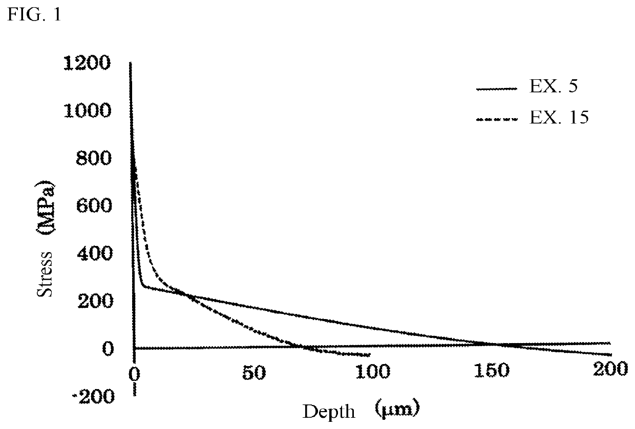
[0144]Examples 15 to 19 are results described on the basis of PTL 1 (US 2015 / 0239775 A). These are corresponding to Sample b, Sample f, Sample g, Sample i, and Sample j, respectively in PTL 1. Values of A1, B1, A2, B2, C, A1 / B1, and A2 / B2 were determined by digitalizing the stress value profiles (FIGS. 5c, 9b, 10b, 11, and 12b) described in PTL 1 with an image analysis software and approximating the digitalized stress value profiles using the function (I). The results are shown in Table 3. In addition, the stress profile of the chemically strengthened glass of Example 15 is illustrated in FIG. 1.

(CS and DOL)

[0145]CS and DOL of the chemically strengthened glasses of Examples 1 to 24 are shown in Tables 2 to 3. CS and DOL were evaluated using a surface stress meter FSM-6000, manufactured by Orihara Industrial Co., Ltd. and SLP1000 which is a measuring device utilizing scattered-light photoelasticity, manufactured by Orihara Industrial Co., Ltd. The depth at which the stress value CSx ...


PUM

PropertyMeasurementUnit
mole percentageaaaaaaaaaa
thicknessaaaaaaaaaa
thicknessaaaaaaaaaa

Abstract

The present invention relates to a chemically strengthened glass satisfying A1 [MPa] of 600 or more, A2 [MPa] of 50 or more, B1 [μm] of 6 or less, B2 [μm] of 10% or more of t [μm], C [MPa] of −30 or less, and A1 / B1 [MPa / μm] of 100 or more when the chemically strengthened glass has a thickness t [μm] and a profile of a stress value [MPa] at a depth x [μm] from a glass surface is approximated by an error least-squares method in a region of 0<x<3t / 8 using the following function while defining a compressive stress as positive and a tensile stress as negative: A1erfc(x / B1)+A2erfc(x / B2)+C, in which erfc is a complementary error function, and relations of A1>A2 and B1<B2 are satisfied.

Description

TECHNICAL FIELD[0001]The present invention relates to a chemically strengthened glass.BACKGROUND ART[0002]In recent years, a cover glass including a chemically strengthened glass has been used for enhancing protection and beauty of a display device of a mobile device such as a mobile phone, a smart phone, a personal digital assistant (PDA), and a tablet terminal. The chemically strengthened glass is a glass in which a surface layer is formed on a glass surface by means of ion exchange for the purpose of increasing a strength of the glass. The surface layer includes at least a compressive stress layer which exists on the glass surface side and in which a compressive stress is generated owing to ion exchange, and a tensile stress layer which exists adjacent to the compressive stress layer on the glass internal side and in which a tensile stress is generated. The strength of the chemically strengthened glass strongly depends on a compressive stress value (hereinafter referred to as “st...

Claims


Application Information

Patent Timeline
Patent Type & Authority Patents(United States)
IPC IPC(8): C03C21/00C03C3/083C03C3/085C03C3/091C03C3/093C03C3/097
CPCC03C21/002C03C3/083C03C3/085C03C3/091C03C3/093C03C3/097C03C21/00C03C3/087G09F9/00C03C3/095
Inventor IMAKITA, KENJIMURAYAMA, SUGURUKASHIMA, IZURUKANEHARA, KAZUKI
Owner AGC INC
Why Eureka
Try Eureka