Heterogeneous electrocaloric effect heat transfer

A technology of electrocaloric effect and heat transfer, which is applied to machines using electric/magnetic effects, lighting and heating equipment, energy-saving heating/cooling, etc., and can solve problems such as no dissipation, removal of heat energy and inability to operate efficiently

Inactive Publication Date: 2014-05-28
EMPIRE TECH DEV LLC
View PDF6 Cites 6 Cited by
  • Summary
  • Abstract
  • Description
  • Claims
  • Application Information

AI Technical Summary

Problems solved by technology

Thermal rectifying materials can be used to prevent backflow of thermal energy from adjacent electrocaloric effect materials in a direction towards the cooled source, however, during periods in which no voltage is applied to electrocaloric effect materials close to the heat source, thermal energy may be reabsorbed by the heat source , or at least not efficiently dissipated from the heat source
As a result, heat transfer devices utilizing conventional electrocaloric effect materials may not operate efficiently in removing thermal energy from a heat source

Method used


Image

  • Heterogeneous electrocaloric effect heat transfer
  • Heterogeneous electrocaloric effect heat transfer
  • Heterogeneous electrocaloric effect heat transfer

Examples


Embodiment Construction

[0020] In the following detailed description, reference is made to the accompanying drawings which form a part hereof. In the drawings, similar symbols typically identify similar components, unless context dictates otherwise. The illustrative embodiments described in the detailed description, drawings, and claims are not meant to be limiting. Other embodiments may be utilized, and other changes may be made, without departing from the spirit or scope of the subject matter presented here. It is to be readily understood that the various aspects of the disclosure as generally described herein and illustrated in the drawings may be arranged, substituted, combined, separated and designed in various configurations, all of which are expressly contemplated herein.

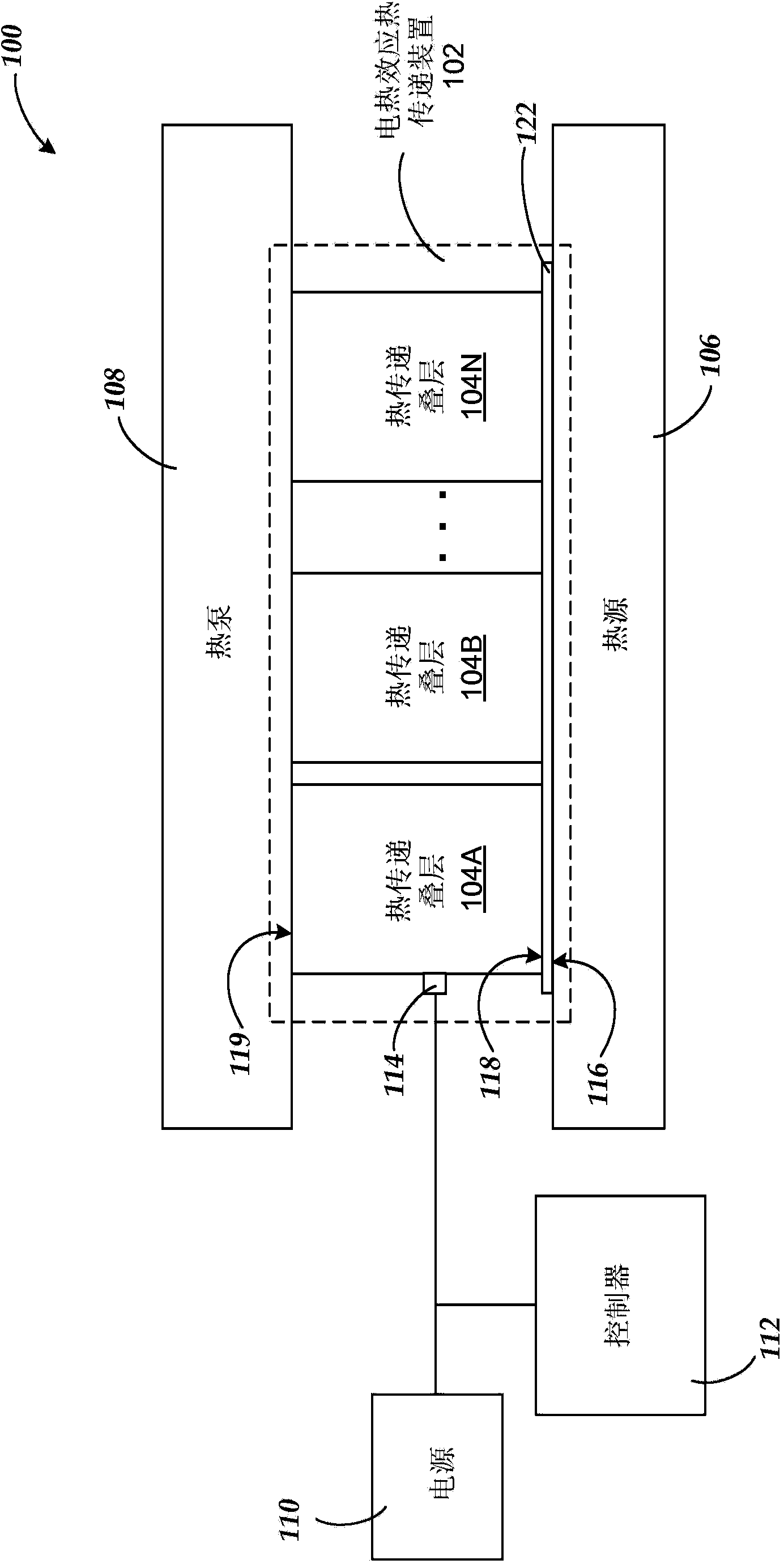
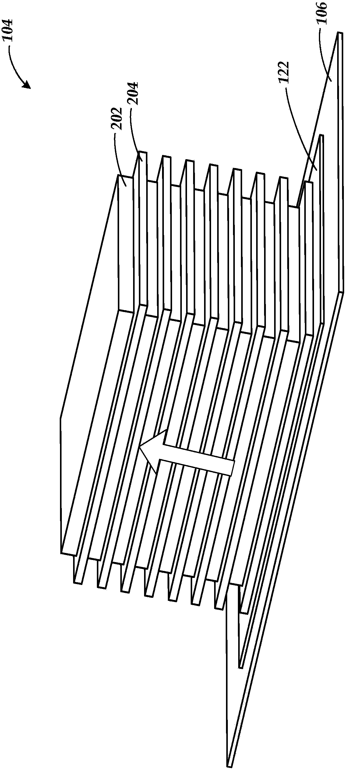
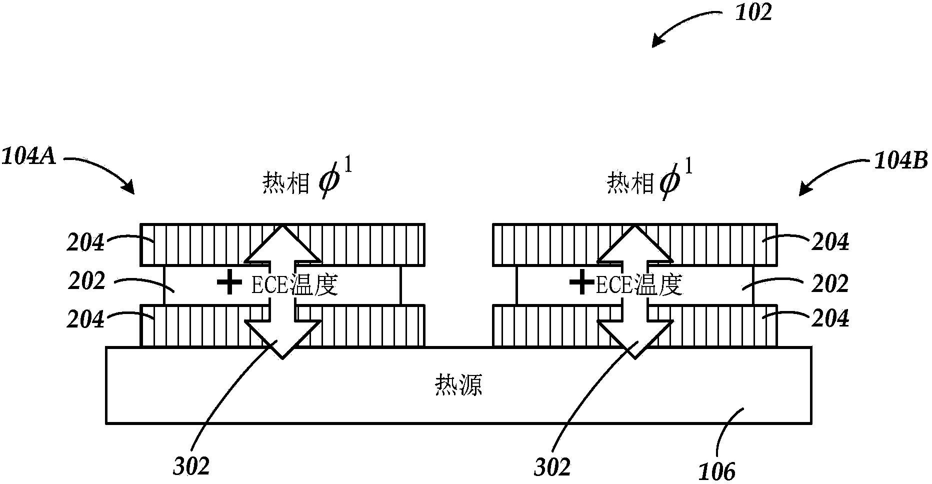
[0021] The present disclosure is generally particularly focused on electrocaloric effect heat transfer techniques that utilize the coordinated application of phased electrical signals to adjacent heat transfer stacks coupl...


PUM


Abstract

Technologies are generally described herein for electrocaloric effect heat transfer devices, methods, and systems that may be effective to efficiently transfer and distribute thermal energy from a heat source utilizing coordinated application of out of phase electric signals to adjacent heat transfer stacks coupled with a thermal distribution layer. Some electrocaloric effect heat transfer stacks may include alternating layers of electrocaloric effect material and thermal rectifier material. The out of phase electric signals produce electric fields that bias the electrocaloric effect material of one heat transfer stack to a hot phase, emitting thermal energy, while biasing the electrocaloric effect material of an adjacent heat transfer stack to a cold phase, absorbing thermal energy. The thermal distribution layer allows for thermal energy from the material in the hot phase to be distributed to the material of the adjacent stack in the cold phase rather than back to the heat source.

Description

[0001] Cross References to Related Applications [0002] This application is related to co-pending application Serial No. PCT / US2010 / 039200, filed June 18, 2010, entitled "Electrocaloric Effect Materials and Thermal Diodes," filed December 17, 2010 Corresponding U.S. national phase application Serial No. 12 / 999,684 entitled "Electrocaloric Effect Materials and Thermal Diodes" and filed on September 21, 2011 entitled "Electrocaloric Effect Heat Transfer Device Dimensional Stress Control (Dimensional Stress Control of Electrocaloric Effect Heat Transfer Devices)", each of which is hereby incorporated by reference in its entirety. Background technique [0003] Unless otherwise indicated herein, the materials described in this section are not prior art to the claims in this application and are not admitted to be prior art by inclusion in this section. [0004] Electrocaloric effect materials are materials that are capable of undergoing a temperature change when subjected to an ap...

Claims


Application Information

Patent Timeline
Patent Type & Authority Applications(China)
IPC IPC(8): F25B21/00
CPCF25B21/00F25B2321/001Y02B30/66F25B21/02Y02B30/00
Inventor E·克鲁格里克
Owner EMPIRE TECH DEV LLC
Why Eureka
Try Eureka