A method for detecting and correcting the positioning accuracy of the rotary axis of a five-axis machine tool

A positioning accuracy and rotation axis technology, which is applied in the direction of measuring/indicating equipment, metal processing machinery parts, other manufacturing equipment/tools, etc., can solve the problem that fixtures cannot be used universally, inspection and correction are difficult, and rotation axis positioning accuracy cannot be corrected and compensated and other problems, to achieve the effect of simple and fast correction and compensation, saving inspection

Active Publication Date: 2016-07-06
JIANGXI CHANGHE AVIATION IND
View PDF4 Cites 2 Cited by
  • Summary
  • Abstract
  • Description
  • Claims
  • Application Information

AI Technical Summary

Problems solved by technology

Using a laser interferometer to check the positioning accuracy of a linear axis is very simple and does not require additional fixtures, but it is extremely difficult to use a laser interferometer to check and correct the positioning accuracy of a rotary axis
Checking and correcting the positioning accuracy of the rotary axis requires the use of a rotary axis angle probe. This probe requires a special tooling fixture that matches the structural characteristics of the machine tool's rotary axis. Different machine tools have different structures of the rotary axis, and the tooling fixtures cannot be used universally. Some machine tool parts need to be disassembled when installing the fixture
Generally, users will not manufacture a large number of special fixtures, so they cannot correct and compensate the positioning accuracy of the rotating shaft. In this way, the risk is relatively high when the accuracy requirements are high, especially when replacing the position detection parts of the rotating shaft. detection

Method used


Image

  • A method for detecting and correcting the positioning accuracy of the rotary axis of a five-axis machine tool
  • A method for detecting and correcting the positioning accuracy of the rotary axis of a five-axis machine tool
  • A method for detecting and correcting the positioning accuracy of the rotary axis of a five-axis machine tool

Examples


Embodiment 1

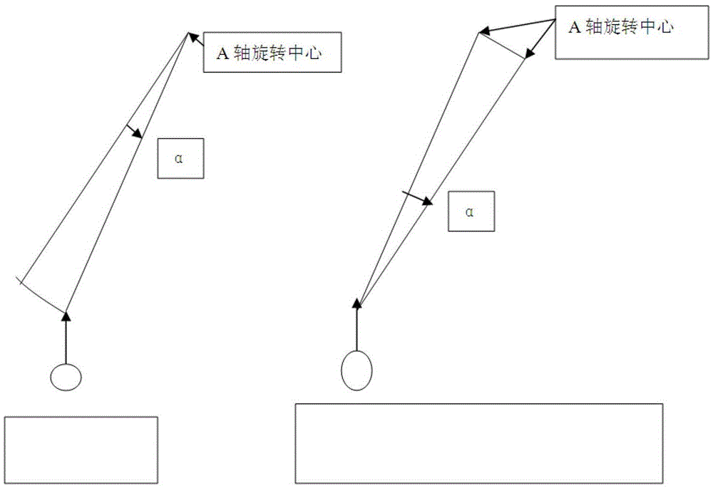
[0046] Embodiment 1, correcting the positioning accuracy of the A-axis of a five-axis vertical AC-axis machine tool. Proceed as follows:

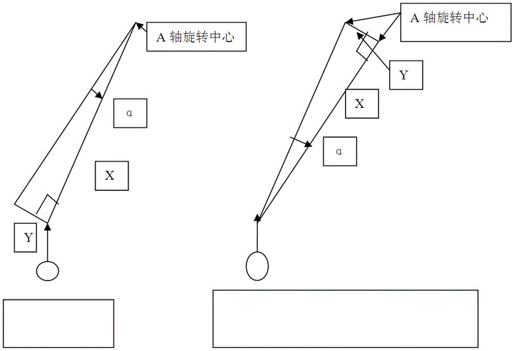
[0047] Step 1: Detect and correct the vertical precision between the spindle of the machine tool and the X-axis, and the precision is 0.02 / 300mm.

[0048] Step 2, detecting and correcting the vertical accuracy of the spindle of the machine tool and the Y-axis, with an accuracy of 0.02 / 300mm.

[0049] Step 3: Detect and correct the perpendicularity between the rotation of the C-axis and the X-axis, with an accuracy of 0.02 / 600mm.

[0050]Step 4: Detect and correct the perpendicularity between the C-axis rotation and the Y-axis, with an accuracy of 0.02 / 600mm.

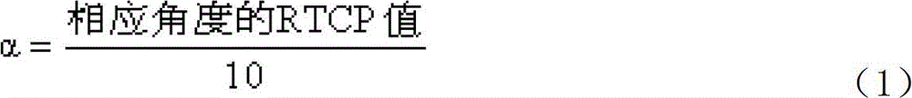
[0051] Step 5: Detect and correct the zero position of the rotary coordinates of the machine tool, so that the pointer of the dial gauge is pressed against the straight rod, the Z axis of the machine tool moves up and down by 250mm, and the pointer of the gauge fluctuates within 0.0...


PUM


Abstract

The invention belongs to the technical field of machine tool detection, and relates to a detection and correction method of locating accuracy of a rotating shaft of a five-axis machine tool. According to the detection and correction method, an angle RTCP value of the rotating shaft in the horizontal or vertical state is measured by means of a straight bar and used as a reference value of RTVP accuracy; the RTCP accuracy of the machining tool is detected by means of a ball bar and a dial indicator, and measurement is conducted every five degrees; by means of the relation between the angle RTCP accuracy and the locating accuracy of the rotating shaft, the locating accuracy of the rotating shaft is corrected. By means of the detection and correction method, correction and compensation of the locating accuracy of the rotating shaft of the five-axis machine tool can be conducted easily, conveniently and rapidly, the detected and corrected accuracy of the rotating shaft of the five-axis machine tool can meet requirements of part manufacturing, and detection and correction time and related costs are saved.

Description

technical field [0001] The invention belongs to the technical field of machine tool detection, and relates to a method for detecting and correcting the positioning accuracy of a rotating shaft of a five-axis machine tool. Background technique [0002] At present, there are more and more five-coordinate CNC machine tools, and the positioning accuracy of the machine tools needs to be corrected and compensated regularly. The calibration and compensation methods generally use laser interferometers. Using a laser interferometer to check the positioning accuracy of a linear axis is very simple and does not require additional fixtures, but it is extremely difficult to use a laser interferometer to check and correct the positioning accuracy of a rotary axis. Checking and correcting the positioning accuracy of the rotary axis requires the use of a rotary axis angle probe. This probe requires a special tooling fixture that matches the structural characteristics of the machine tool's r...

Claims


Application Information

Patent Timeline
Patent Type & Authority Patents(China)
IPC IPC(8): B23Q17/00
CPCB23Q17/007B23Q23/00
Inventor 林超青胡辉黎雪明蔡志杰秦海波余娜
Owner JIANGXI CHANGHE AVIATION IND
Why Eureka
Try Eureka