A method for forming a hollow composite material pipe body

A composite material and molding method technology, which is applied in the field of composite material manufacturing, can solve the problems of strong friction between the pipe body and the core mold, insufficient extrusion amount, and poor product glue, so as to reduce the input cost, improve the success rate, and reduce the production cycle. the effect of shortening

Active Publication Date: 2016-06-08
JIANGXI CHANGHE AVIATION IND
View PDF3 Cites 0 Cited by
  • Summary
  • Abstract
  • Description
  • Claims
  • Application Information

AI Technical Summary

Problems solved by technology

However, due to the different thermal expansion coefficients of the mandrel, composite material, and shape of the mold, the product is either over-extruded, the product is poor in glue, and has a large porosity, or the amount of extrusion is insufficient, and the product is under-pressurized and delaminated.
In order to meet the design requirements of the product, the corresponding process compensation is often carried out in the tooling design, and the compensation coefficient needs multiple process tests to find out, which is costly and inefficient
In addition, because the contact area between the composite pipe body and the mandrel is too large, the friction between the pipe body and the mandrel is strong, and it is difficult to demould

Method used


Image

  • A method for forming a hollow composite material pipe body
  • A method for forming a hollow composite material pipe body

Examples


Embodiment 1

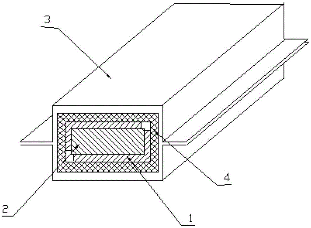
[0028] right figure 1 The hollow square tube shown is produced, and the forming steps are as follows:

[0029] 1.1 Use metal aluminum plate or stainless steel sheet to preform according to the inner profile of the square tube, and manufacture a half-profile "L"-shaped metal partition with a thickness of 0.5mm;

[0030] 1.2 Manufacture the metal mandrel and composite material shape tooling that removes the thickness of the partition: the thickness of 0.5mm must be subtracted when the metal mandrel is manufactured, and the surface formed by the metal mandrel plus the metal partition conforms to the theoretical internal shape of the product, and the composite material The shape tooling is the upper and lower clamping structure, and the profile of the clamping structure is the external profile of the product;

[0031] 1.3 Cover two "L"-shaped metal partitions on the metal mandrel, and connect the metal partitions with adhesive tape to form a whole;

[0032] 1.4 Lay layers on met...

Embodiment 2

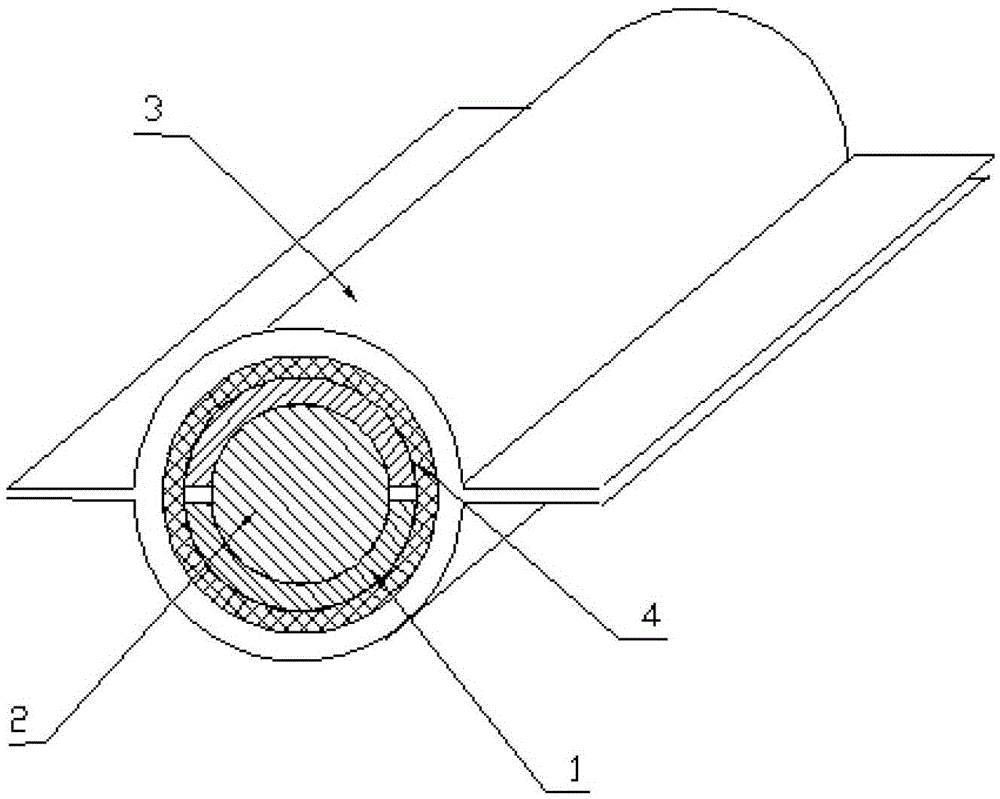
[0038] right figure 2 The hollow circular tube shown is produced, and the forming steps are as follows:

[0039] 2.1 Use metal aluminum plate or stainless steel sheet to preform according to the inner surface of the round tube, and manufacture a metal partition with a thickness of 0.5mm and a semicircular surface;

[0040] 2.2 Manufacture the metal mandrel and composite material shape tooling that removes the thickness of the partition: the thickness of 0.5mm must be subtracted when the metal mandrel is manufactured, and the surface formed by the metal mandrel plus the metal partition conforms to the theoretical internal shape of the product, and the composite The shape tooling is the upper and lower clamping structure, and the profile of the clamping structure is the external profile of the product;

[0041] 2.3 Cover two semicircular metal partitions on the metal mandrel, and connect the metal partitions with adhesive tape to form a whole;

[0042] 2.4 Lay layers on the p...


PUM


Abstract

The invention belongs to the field of composite material production, and relates to a molding method for a hollow composite material pipe. The molding method comprises: 1.1) producing a metal separation plate with a certain thickness and a half-molding surface; 1.2) producing a separation plate thickness-removed metal core mold and a composite material shape tooling; 1.3) fixing the metal separation plate with the half-molding surface on the metal core mold; 1.4) stacking the composite material on the metal separation plate; 1.5) placing the metal core mold with the stacked layer into the composite material shape tooling, and closing the mold; 1.6) pulling the metal core mold out from the metal separation plate; 1.7) placing a tubular vacuum bag into the original core mold position of the metal separation plate; and 1.8) carrying out vacuum pumping and curing molding. The molding method has characteristics of high production processing efficiency, and low tooling design and manufacturing cost.

Description

technical field [0001] The invention belongs to the field of composite material manufacturing and relates to a forming method of a hollow composite material pipe body. Background technique [0002] The forming of hollow composite tubes has always been a problem, and many aircraft have a large number of such tubes. The composite material pipe body is usually formed by a positive mold. In order to improve the quality of the pipe body, it can be formed by a core mold plus a shape clamping method. However, due to the different thermal expansion coefficients of the mandrel, the composite material, and the shape of the clamping mold, the product is either over-extruded, poor in rubber, and has a large porosity, or insufficiently extruded, and the product is under-pressurized and delaminated. In order to meet the design requirements of the product, corresponding process compensation is often carried out in the tooling design, and the compensation coefficient needs multiple process...

Claims


Application Information

Patent Timeline
Patent Type & Authority Patents(China)
IPC IPC(8): B29C70/34B29L23/00
CPCB29C70/342B29L2023/00
Inventor 祝景萍管海新江跃汪心文徐大鹏冯汉斌易卫余春雷陶燕周阳富郑樵生李晓娜蒋克全赵学良
Owner JIANGXI CHANGHE AVIATION IND
Why Eureka
Try Eureka