Method and brake system controller for venting vehicle hydraulic brake system

A brake system, hydraulic brake technology, applied in the direction of pump/compressor arrangement, etc., can solve the problems of increasing pedal operation stroke, interference, unrealistic necessary steps, etc., and achieve the effect of reducing the amount of residual gas

Active Publication Date: 2019-09-17
FORD GLOBAL TECH LLC
View PDF5 Cites 0 Cited by
  • Summary
  • Abstract
  • Description
  • Claims
  • Application Information

AI Technical Summary

Problems solved by technology

Air bubbles remaining in the system are compressed when the brake pressure increases, leading to an elastic behavior of the brake transmission path and thus to an increased pedal actuation travel, which is perceived by the driver as a nuisance and in extreme cases constitutes Security Risk
[0003] For various reasons, a perfect air-free filling of the brake system cannot always be guaranteed, especially during the first filling of the brake system with hydraulic fluid during vehicle production
Even if the safety-critical threshold is not exceeded, this will lead to abnormally long pedal actuation travel and thus driver discomfort, which can lead to a period of time in the workshop, which should generally be avoided for new cars
[0004] However, the traditional venting process relies on introducing hydraulic fluid from a pressure source at one point in the brake system, opening one or more vent valves at other points, and then enforcing fluid flow until the vent valves no longer emit air bubbles , the process is relatively costly, and therefore, based on time and cost considerations, such a venting process is not practical as a necessary step in vehicle production

Method used


Image

  • Method and brake system controller for venting vehicle hydraulic brake system
  • Method and brake system controller for venting vehicle hydraulic brake system
  • Method and brake system controller for venting vehicle hydraulic brake system

Examples


Embodiment Construction

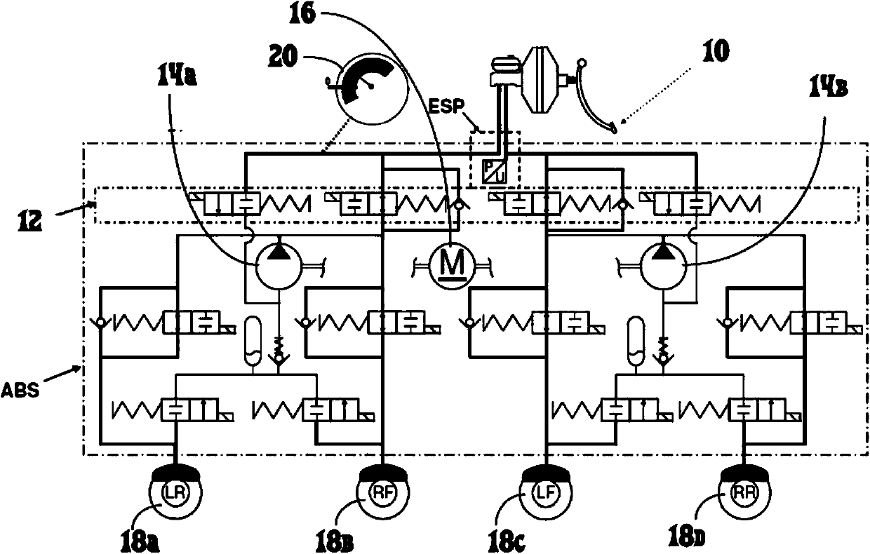
[0029] figure 1 A schematic diagram showing the hydraulic brake system (service brake) of a car with ABS and ESC. The brake system is shown as an example only; the invention can be used in many different brake system configurations. According to legal regulations, two independent brake circuits are equipped. In an exemplary embodiment, each brake circuit provides diagonally opposite brakes 18a to 18d in an X-shaped configuration. On the one hand, the brake pedal 10 can be used to realize the operation of the brake. In a known manner, the brake pressure is applied to the two brake circuits independently of each other through a brake booster and a tandem master cylinder. figure 1 In the middle, a thicker line is used to highlight the line affected by the pressure. The generated pressure is indicated by the pressure gauge 20 indicated by the symbol, and, in the case where the unit mentioned has "ESP", the generated pressure is also measured by a pressure sensor (pressure / voltage c...


PUM


Abstract

A method for venting at least part of a hydraulic brake system of a vehicle, wherein the brake system comprises at least one brake circuit, the pressure of which can be passed through at least one electric motor-driven pump device, in particular an ESC pump (14a, 14b) optionally increased, for a specified period of time, increased pressure can be applied by the pump means (14a, 14b) to the portion of the brake system that is to be vented without opening the vent valve.

Description

Technical field [0001] The present invention relates to a method for exhausting at least a part of a hydraulic brake system of a vehicle and a brake system controller, wherein the brake system includes at least one brake circuit, a pump device driven by at least one electric motor, and the brake circuit The pressure can be selectively increased. Background technique [0002] For vehicles, especially hydraulic brake systems used in automobiles, it is known that correct exhaust is very important. When the brake pressure increases, the air bubbles remaining in the system are compressed, resulting in the elastic behavior of the brake transmission path, and therefore resulting in an increased pedal operation stroke, which is considered by the driver to be an interference and in extreme cases also constitutes Security Risk. [0003] For various reasons, it is not always possible to guarantee the perfect gas-free filling of the brake system, especially when the brake system is first fil...

Claims


Application Information

Patent Timeline
Patent Type & Authority Patents(China)
IPC IPC(8): B60T17/02
Inventor 金姆·史蒂芬·琼斯克莱夫·约翰·巴顿路德维格·费恩
Owner FORD GLOBAL TECH LLC
Why Eureka
Try Eureka