Variable-cross-section channel of multi-stage cusped magnetic field plasma pusher

A technology of plasma and tangent magnetic field, which is applied in the field of plasma thrusters, can solve the problems of gas working medium leakage and other problems, and achieve the effects of eliminating secondary plume, increasing thrust, high specific impulse and benefit

Active Publication Date: 2014-06-04
HARBIN INST OF TECH
View PDF4 Cites 3 Cited by
  • Summary
  • Abstract
  • Description
  • Claims
  • Application Information

AI Technical Summary

Problems solved by technology

[0003] The present invention is to solve the problem that the gas working medium escapes easily on the wall surface of the straight channel of the existing tangential magnetic field plasma pusher, and now provides a variable cross-section channel of the multi-stage cusp magnetic field plasma pusher

Method used


Image

  • Variable-cross-section channel of multi-stage cusped magnetic field plasma pusher
  • Variable-cross-section channel of multi-stage cusped magnetic field plasma pusher
  • Variable-cross-section channel of multi-stage cusped magnetic field plasma pusher

Examples


specific Embodiment approach 1

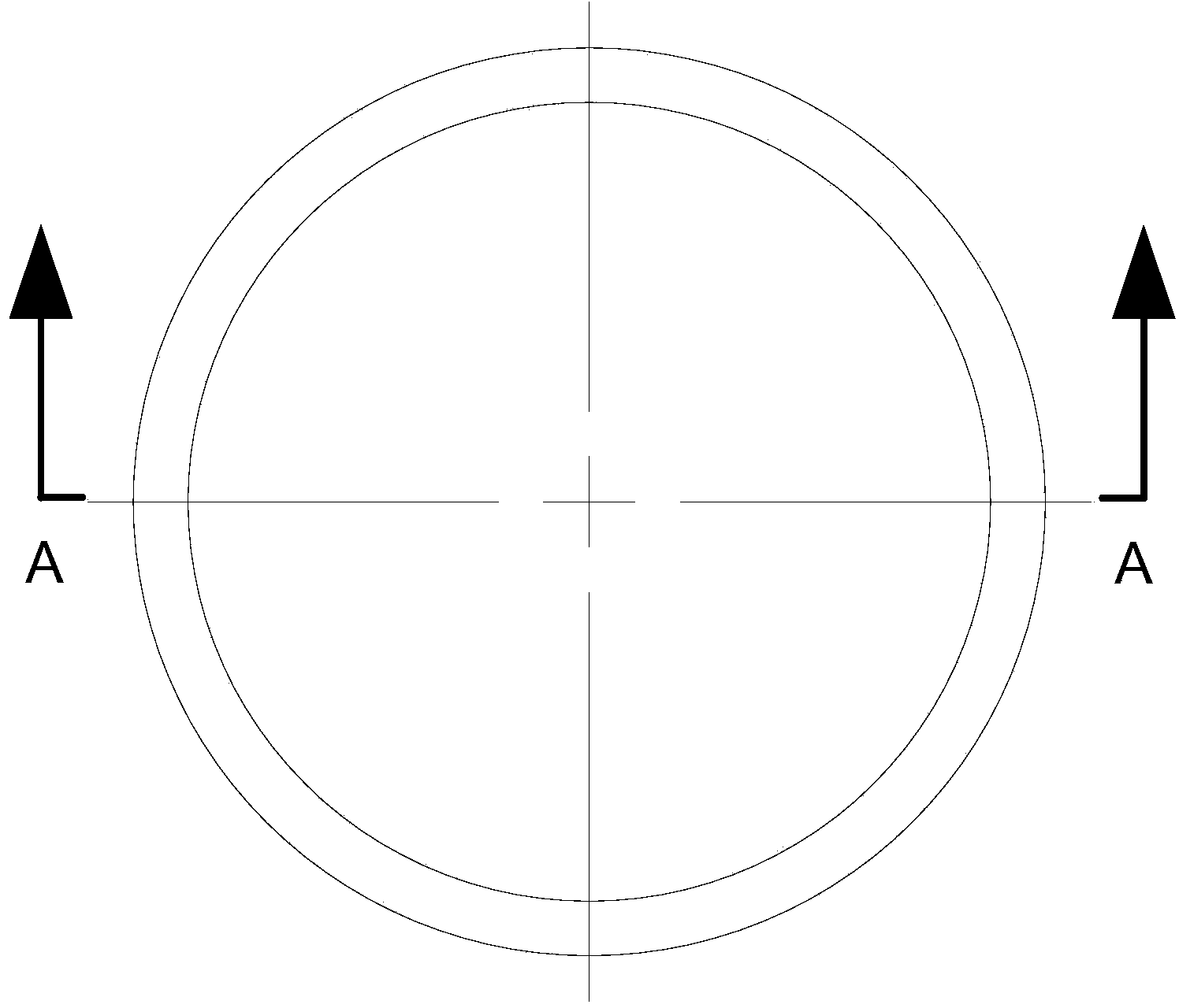
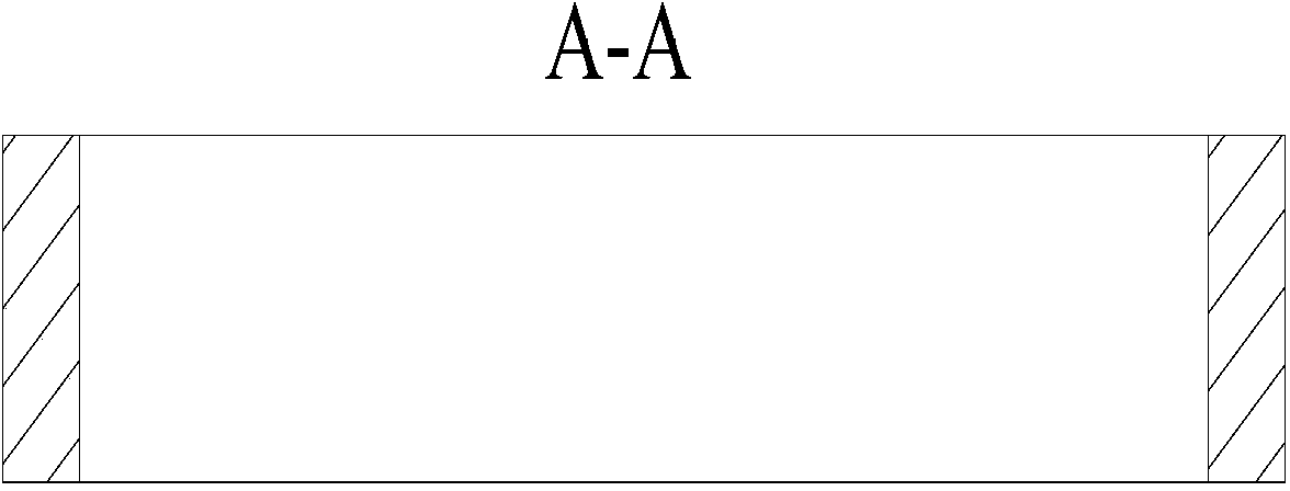
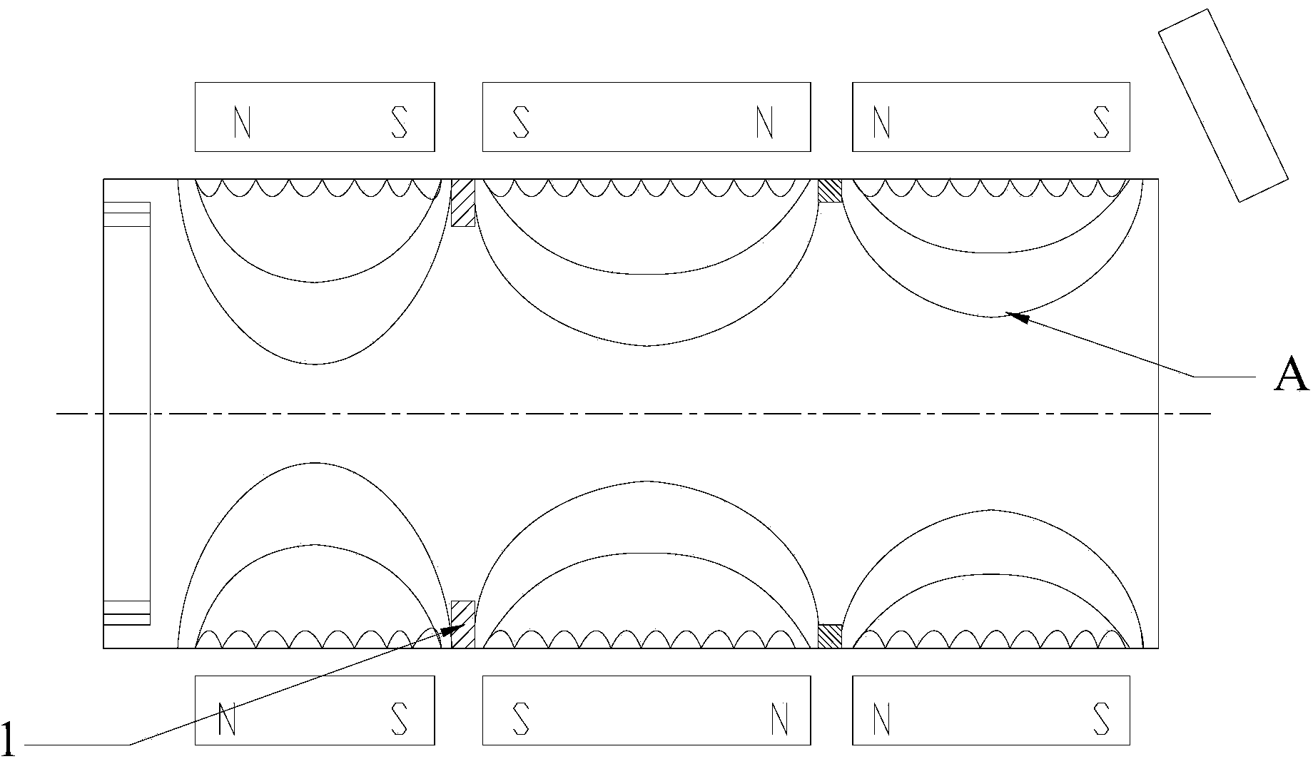
[0016] Specific implementation mode one: refer to figure 1 , figure 2 and image 3 Specifically explain this embodiment, the variable cross-section channel of the multi-stage tangent magnetic field plasma pusher described in this embodiment, the inner wall of the ceramic channel of the plasma pusher is embedded with n circular rings along the axial direction of the ceramic channel Boss 1, the inner side walls of the n bosses 1 are all cylindrical surfaces, the difference between the inner diameter and outer diameter of the n bosses 1 is between 2mm and 10mm, and the inner diameters of the n bosses 1 are along the ceramic channel The anode to cathode gradually increases, where n is a positive integer.

[0017] In this embodiment, if the difference between the inner diameter and the outer diameter of the boss is too large, it will affect the axial movement of ions, and if it is too small, the improvement of the wall gas leakage phenomenon will not be obvious, so it is optimal...

specific Embodiment approach 2

[0018] Embodiment 2: This embodiment is a further description of the variable cross-section channel of the multi-stage tangential magnetic field plasma pusher described in Embodiment 1. In this embodiment, each boss 1 corresponds to the adjacent A magnetic tip between two poles.

[0019] The boss located at the magnetic tip of the ceramic channel can improve the ionization efficiency.

specific Embodiment approach 3

[0020] Embodiment 3: This embodiment is to further explain the variable cross-section channel of the multi-stage tangential magnetic field plasma pusher described in Embodiment 1. In this embodiment, the inner wall of the ceramic channel of the plasma pusher Wavy.

[0021] When the straight ring boss is used, the inner wall of the ceramic channel is made into a wave surface, which can make the wall gas flow into a turbulent flow and more fully ionize the wall gas.


PUM


Abstract

The invention provides a variable-cross-section channel of a multi-stage cusped magnetic field plasma pusher, belongs to the field of cusped magnetic field plasma pushers, and particularly relates to a variable-cross-section channel of a cusped magnetic field plasma pusher. The problem that a gas working medium easily leaks from a wall surface of a straight channel of the existing cusped magnetic field plasma pusher is solved. The inner side wall of the ceramic channel of the plasma pusher is fixedly embedded with n ring-shaped bosses along the axial direction of the ceramic channel; inner side walls of the n bosses are cylindrical surfaces; inner side walls of axial sections of the n bosses are arch-shaped; and n is a positive integer. The section of the channel is changed by adding the bosses in the channel, so that the section of the wall surface of the straight ceramic channel of the plasma pusher is variable, the gas working medium can be sufficiently ionized on the wall surface, and the gas of the wall surface can be prevented from leaking, so that the secondary plume flow possibly existing in an exit is eliminated. The variable-cross-section channel is applicable to the cusped magnetic field plasma pusher.

Description

technical field [0001] The invention belongs to the field of tangent magnetic field plasma pushers, in particular to a variable-section channel of cusp magnetic field plasma pushers. Background technique [0002] The tangential magnetic field plasma thruster is a new type of electric propulsion concept that has emerged internationally. It is different from traditional electric propulsion devices. It mainly includes ceramic discharge channels and permanent magnets with opposite polarities. Approaching the helical movement of the anode, during this process, the anode releases the gas working fluid and collides with the electrons to ionize, and the ionized ions will be accelerated and ejected under the action of the axial electric field to form a thrust. Due to the magnetic confinement of the axial magnetic field and the magnetic mirror effect of the magnetic tip, the collision of electrons with the inner wall of the channel can be avoided, resulting in longer engine life, bett...

Claims


Application Information

Patent Timeline
Patent Type & Authority Applications(China)
IPC IPC(8): F03H1/00
Inventor 刘辉陈蓬勃于达仁马成毓赵隐剑孙国顺
Owner HARBIN INST OF TECH
Why Eureka
Try Eureka