Infrared multi-point positioning method

A multi-point positioning and infrared technology, applied in the direction of instruments, electrical digital data processing, data processing input/output process, etc., can solve the problems of large memory consumption, large calculation amount of image method, and inability to recognize real touch objects, etc., to achieve The effect of perfect algorithm

Inactive Publication Date: 2014-06-04
北京华远盛亚科技有限责任公司
View PDF4 Cites 8 Cited by
  • Summary
  • Abstract
  • Description
  • Claims
  • Application Information

AI Technical Summary

Problems solved by technology

Therefore, the image method will not be able to identify the real touch object with the same or close to the grid noise size, even if there is obviously a blocked optical path at this time; in addition, the time difference during high-speed movement will lead to the loss of points after corrosion
The inventors found that the above-mentioned multi-point acquisition scheme has major defects, because the logic method only utilizes the local characteri

Method used


Image

  • Infrared multi-point positioning method
  • Infrared multi-point positioning method
  • Infrared multi-point positioning method

Examples


Embodiment Construction

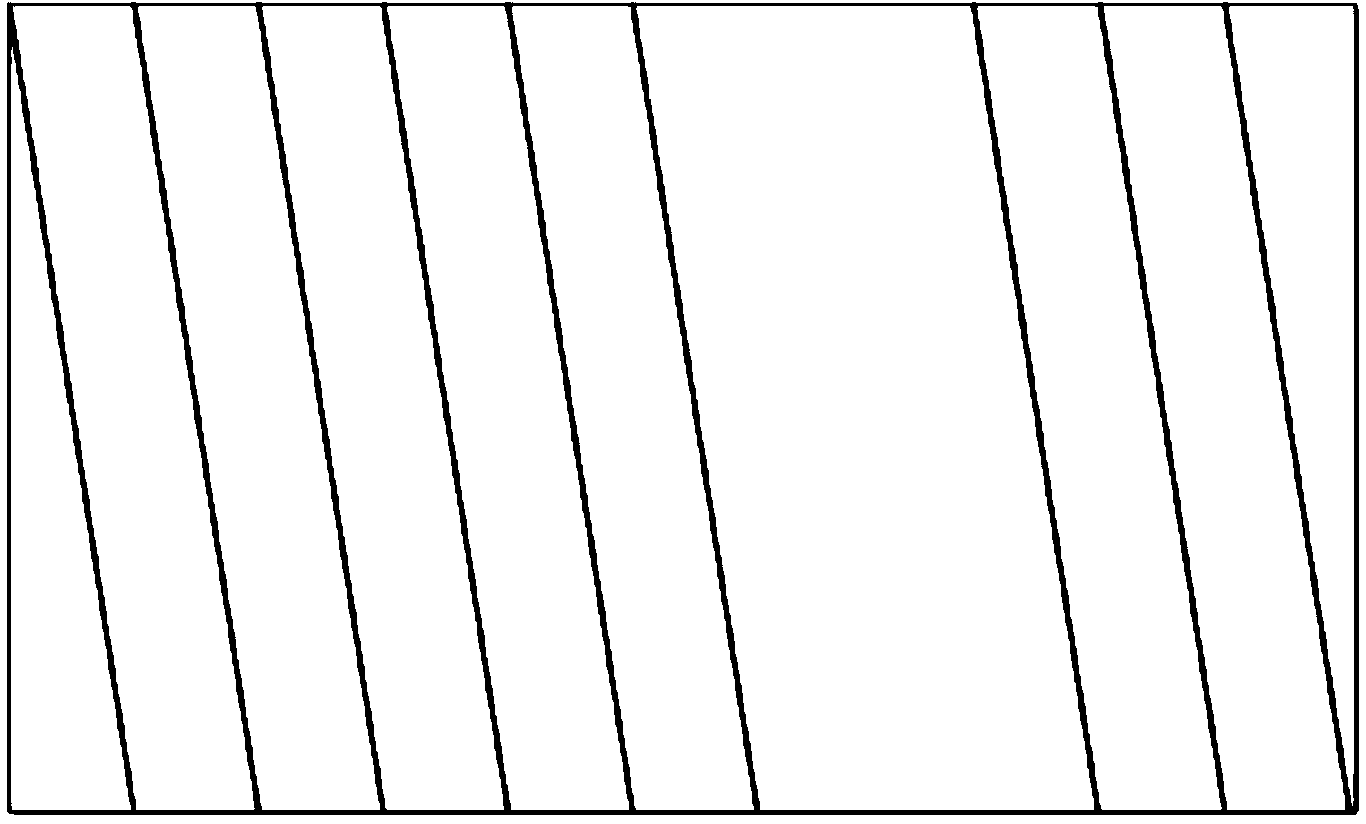
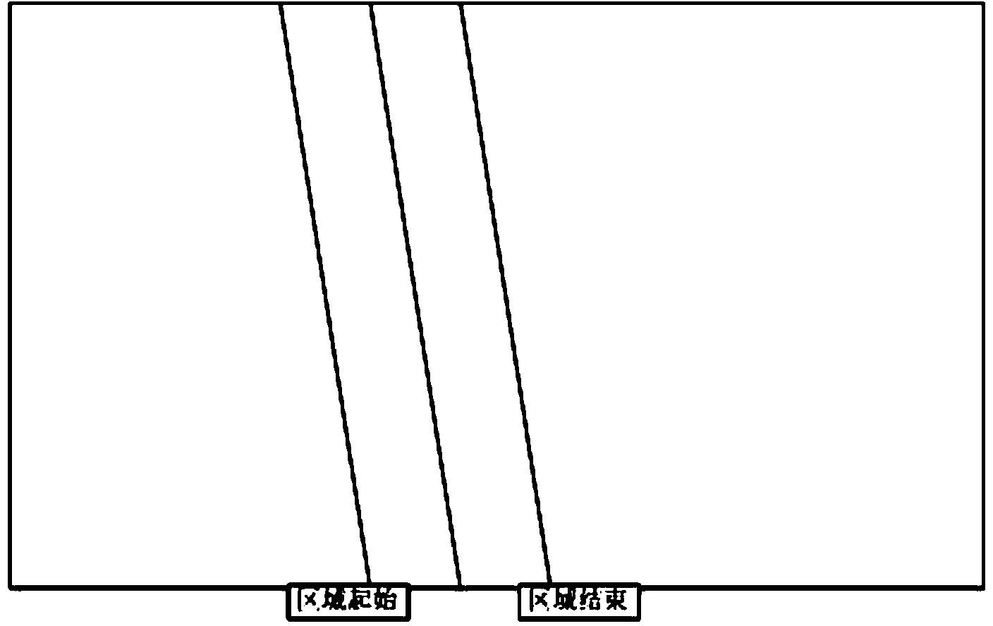
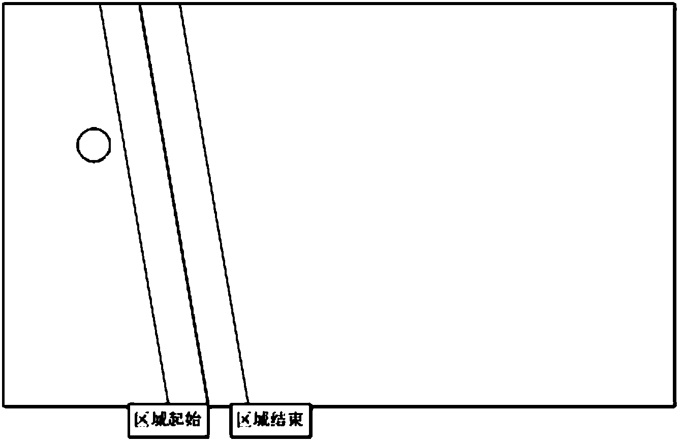
[0020] Such as Figure 1-3 As shown, a kind of infrared multi-point positioning method described in the embodiment of the present invention, described this positioning method comprises the following steps:

[0021] Step 1: Preset the window distance threshold t1, the difference distance threshold t2, and the true point judgment threshold t3;

[0022] Step 2: Determine the reference viewing angles in the horizontal and vertical directions respectively;

[0023] Step 3: How to calculate the standard score of each point from the candidate point set obtained from the horizontal reference angle of view and the vertical reference angle of view;

[0024] Step 4: How to calculate the true integral of each point in the candidate point set derived from the horizontal reference angle of view and the vertical reference angle of view;

[0025] Step 5: Judgment of true and false points.

[0026] Further, in step 1, the integration is performed only when the distance from the occluded are...


PUM


Abstract

The invention relates to an infrared multi-point positioning method. The infrared multi-point positioning method comprises the following steps of presetting a window distance threshold value t1, conducting traversal on each viewing angle in the horizontal direction, conducting statics on area information of each viewing angle, and assuming that the number of obtained areas is K1, K2,..., KN respectively; conducting traversal on each viewing angle in the perpendicular direction, conducting statics on area information of each viewing angle, and enabling the number of the obtained areas to be P1, P2,..., PM respectively; calculating a standard score of each point of a candidate point set; conducting statics on a real integral of each point in the candidate point set; judging the true points and the false points. The method has the advantages that the multi-viewing-angle concept is provided; two viewing angles with the most number in the covered area are used as the standard viewing angles, and the standard viewing angles are utilized for calculating candidate touch points; the concept that the minimum distance between the covered area and the points is a standard distance, and other distances are compared with the standard distance is provided; the concept that auxiliary viewing angles are utilized for conducting integration is provided; the four aspects are most important.

Description

technical field [0001] The invention relates to an infrared multi-point positioning method. Background technique [0002] Existing infrared multi-point recognition technology has two kinds of logical judgment method and image processing method, both of which are based on one-to-many hardware scanning method, obtain obstacle boundary according to optical path data; obtain quasi (candidate) touch point set according to boundary , and set the real touch point threshold; traverse each candidate touch point, and determine the credibility of the current point as a real touch point. The reliability is determined as follows. According to the area formed by the boundary of this point, the set of light paths that should theoretically pass through this area is inversely deduced, and the number of actually blocked light path sets is judged in turn. Divide the actual occlusion number by the theoretical occlusion number, if it is greater than the threshold, it is a real point, otherwise ...

Claims


Application Information

Patent Timeline
IPC IPC(8): G06F3/042
Inventor 张自能杨运肖时航
Owner 北京华远盛亚科技有限责任公司
Why Eureka
Try Eureka