Restoration method for blurred image caused by camera shaking

A technology for camera shake and blurred images, applied in the field of image processing, can solve problems such as low computational efficiency, difficulty in deconvolution of uniformly blurred images, and inability to obtain restoration results, so as to avoid storing high-dimensional sparse matrices and reduce memory usage. Effect

Active Publication Date: 2014-06-04
哈尔滨市超凡视觉科技有限公司
View PDF4 Cites 10 Cited by
  • Summary
  • Abstract
  • Description
  • Claims
  • Application Information

AI Technical Summary

Problems solved by technology

However, a series of recent research and analysis results have proved that the image blur caused by camera shake is a kind of non-uniform blur, that is, in the blurred image, the degree of blur on each pixel is spatially varied, which makes the recovery of camera shake caused by The blurred image becomes a more difficult problem than uniform blurred image deconvolution
Although some methods have been devoted to recovering camera shake blurred images in recent years, some of the mainstream methods, for example, divide the entire image into many overlapping regions and use the method of uniform restoration to estimate the local blur kernel. The constraints of the global image information on the local blur kernel obviously do not make reasonable use of the image information, and a satisfactory restoration result cannot be obtained; other methods based on the mapping motion path model define the blur caused by camera shake as a clear image After a series of weighted sums of homography transformation results, although better restoration results can be obtained, the low computational efficiency of the restoration method based on this model has become a fatal injury. Although there are many methods to improve the algorithm and improve the Computational efficiency, but these methods introduce another disadvantage that limits the wide application of this method: the calculation process needs to store high-dimensional sparse matrices, so that the memory usage of the entire restoration method increases sharply

Method used


Image

  • Restoration method for blurred image caused by camera shaking
  • Restoration method for blurred image caused by camera shaking
  • Restoration method for blurred image caused by camera shaking

Examples


Embodiment Construction

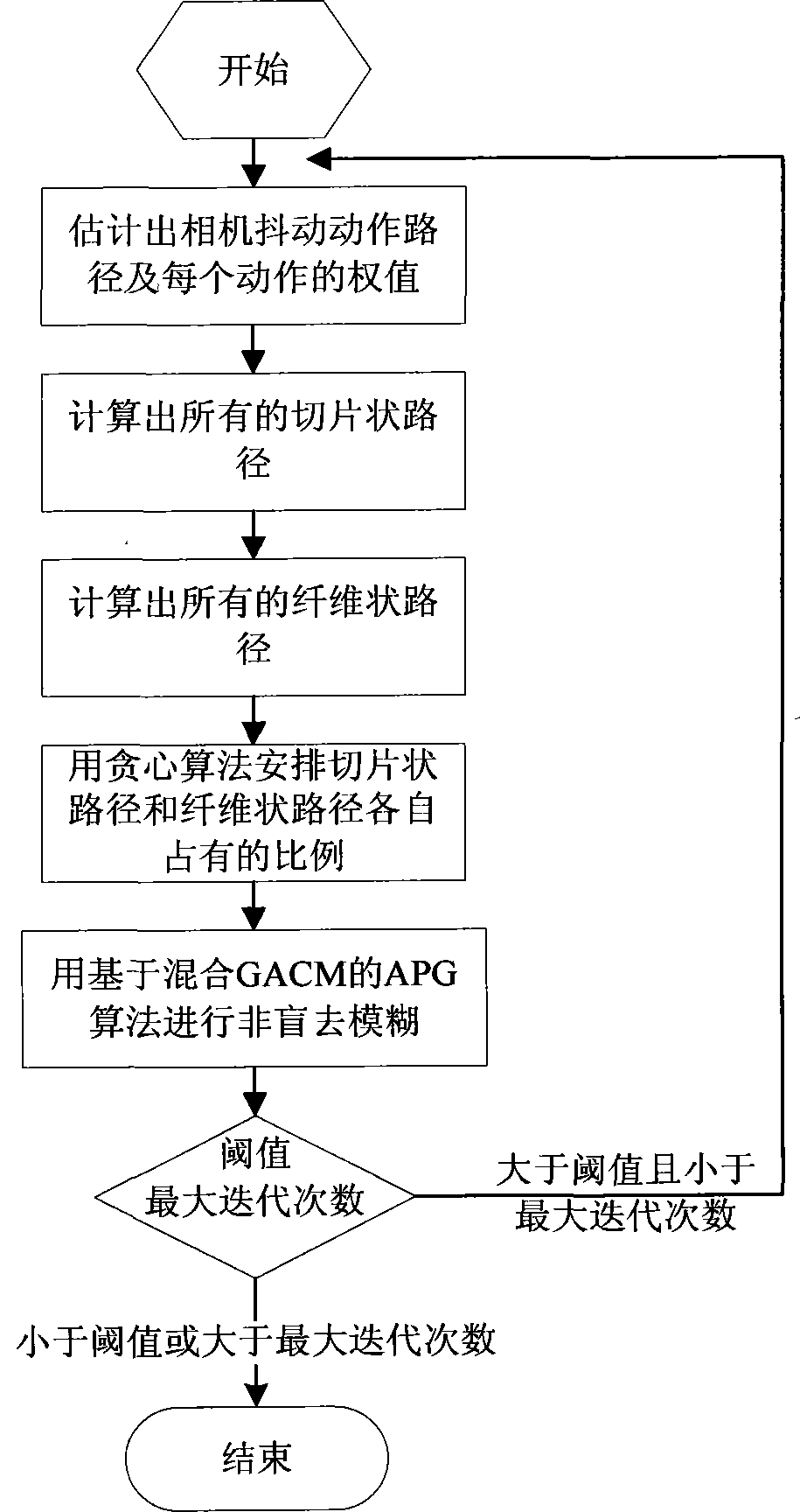
[0076] The concrete implementation process of the present invention sees figure 1 , below in conjunction with accompanying drawing, the specific embodiment of the present invention is described further:

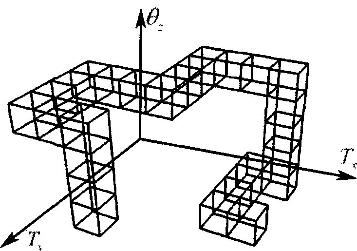
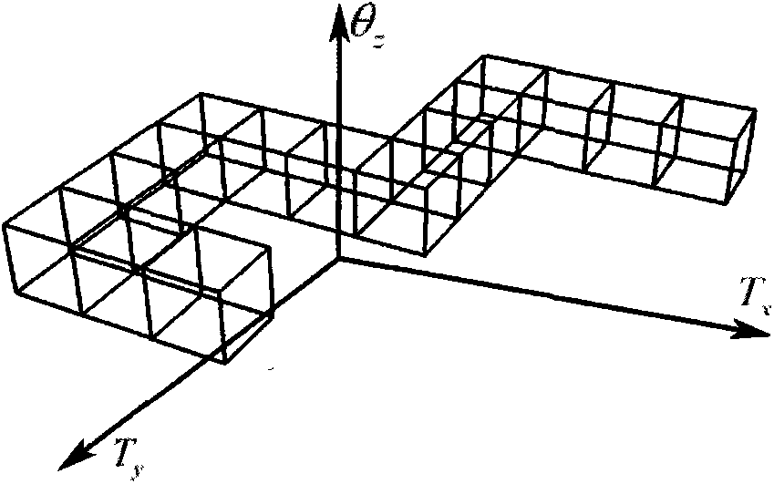
[0077] 1. First, given L∈R n×n , to estimate the camera shake action path, that is, the set P={θ=(θ z , t x , t y )}, as attached figure 2 Shown is a one-dimensional curve, each action on the camera action path is three-dimensional, and can be represented by parameters of the form θ=(θ z , t x , t y ), where θ z is the angle of rotation around the z-axis, t x and t y They are the amount of translation along the x-axis and y-axis respectively, and use the conjugate gradient method to solve the following optimization problem to solve W, which is the weight of each action in the action path:

[0078] min W | | Σ θ ∈ ...


PUM


Abstract

The invention relates to a restoration method for a blurred image caused by camera shaking. In the restoration process of the blurred image caused by camera shaking, if a fuzzy model is designed inappropriately, a restoration result can be bad, computation efficiency is low, and internal storage footprints are increased suddenly, so that it is a problem demanding prompt solution in the field to develop the better restoration method for the blurred image caused by camera shaking. A generalized additive convolution model is designed, and the blurred image caused by camera shaking is restored based on the model. The restoration method includes the steps that motion paths of camera shaking are estimated; all slice-shaped paths and fiber-shaped paths are calculated, and proportions for which the slice-shaped paths and the fiber-shaped paths account for are set through a greedy algorithm; non-blind restoration is performed through an APG algorithm based on mixed GACM. The restoration method is good in restoration visual effect, small in internal storage footprint and suitable for restoring various blurred images caused by camera shaking and takes efficiency and speediness into account.

Description

technical field [0001] The invention relates to an image restoration method, in particular to a restoration method for blurred images caused by camera shaking, and belongs to the field of image processing. Background technique [0002] Image restoration is a very fundamental problem in computer vision and image processing. Image blurring due to various factors such as defocus, camera shake, motion of objects in the image, etc. is unavoidable. In such an era when digital imaging equipment has been widely used, there is no doubt that blurred image restoration technology is a very hot topic. So far, it is still a challenging problem to develop an image restoration technique that is both accurate and robust. Early scientific research assumed that the degree of blurring on each pixel in the blurred image is the same. Based on this assumption, many methods also show strong restoration capabilities for blurred images. However, a series of recent research and analysis results hav...

Claims


Application Information

Patent Timeline
IPC IPC(8): G06T5/00
Inventor 左旺孟邓红张宏志张垒磊石坚
Owner 哈尔滨市超凡视觉科技有限公司
Why Eureka
Try Eureka