S-shaped grounding resistor

A technology for grounding resistors and resistors, which is applied in the direction of resistors, resistor cooling/heating/ventilation devices, I-shaped/sinusoidal resistance elements, etc., which can solve complex manufacturing, short circuit of resistors, and difficult heat dissipation of resistors and other problems, to achieve the effect of reasonable structural design, large flow cross section and good heat dissipation effect

Inactive Publication Date: 2014-06-04
马生平
View PDF0 Cites 3 Cited by
  • Summary
  • Abstract
  • Description
  • Claims
  • Application Information

AI Technical Summary

Problems solved by technology

However, limited by its structure, the structural design is unreasonable, and the temperature rises during actual operation, especially under the instantaneous impact of high current, it can turn red and deform, resulting in a short circuit of the resistor, or even an accident. There are unsafe factors. restricted
In addition, some metal resistors are composed of pieces of metal sheets that are welded and stacked layer by layer. The above-mentioned structure is complicated to manufacture, and the resistors are not easy to dissipate heat, and the denser arrangement will cause dust accumulation, which will easily affect the normal operation of the resistors.

Method used


Image

  • S-shaped grounding resistor
  • S-shaped grounding resistor
  • S-shaped grounding resistor

Examples


Embodiment Construction

[0018] Below in conjunction with accompanying drawing and specific embodiment, further illustrate the present invention, should be understood that these embodiments are only for illustrating the present invention and are not intended to limit the scope of the present invention, after having read the present invention, those skilled in the art will understand various aspects of the present invention Modifications in equivalent forms all fall within the scope defined by the appended claims of this application.

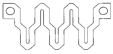
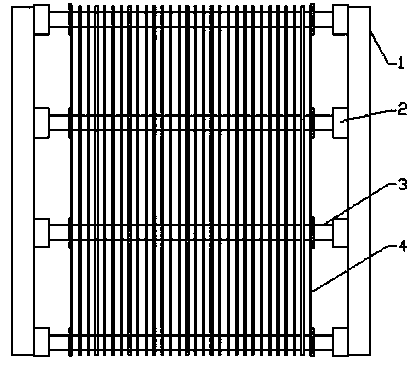
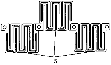
[0019] see figure 1 , figure 2 with image 3 As shown, the S-type grounding resistor of the present invention includes a bracket 1 , an insulator 2 , a supporting link 3 and a combined resistor 4 . Wherein, the combined resistor 4 includes multiple sets of resistors, and the resistors include multiple resistor sheets 5 welded end to end, and the cross section of the resistor sheets 5 is S-shaped.

[0020] The supporting link 3 is arranged on the bracket 1 , and the c...


PUM


Abstract

The invention discloses an S-shaped grounding resistor. The S-shaped grounding resistor comprises a bracket, insulators, a supporting connecting rod and a combined resistor, wherein the combined resistor comprises a plurality of groups of resistors; each resistor comprises a plurality of resistor discs arranged end to end; sections of the resistor discs are S-shaped; the supporting connecting rod is arranged on the bracket; the combined resistor is arranged on the supporting connecting rod; and the insulators are mounted at the two ends of the supporting connecting rod. According to the invention, the S-shaped resistors can be conductively connected with each other through adoption of the S-shaped resistor discs end to end. As the widths of the resistor discs with S-shaped structures are smaller than the resistor discs with W-shaped structures and the number of the S-shaped resistor discs with the same widths is larger than the number of the resistor discs with the W-shaped structures, the through-flow sections of the resistors are large and the temperature rises of the S-shaped resistors are lower than those of short-time and large-current resistors with the W-shaped structures under the same power. In addition, as the resistor discs in the plurality of groups are end to end and arranged in parallel, the S-shaped grounding resistor disclosed by the invention has the advantages of reasonable structural design, good heat radiation effect and no ash deposition and is high pressure resistant and high temperature resistant in the large-current operation process.

Description

technical field [0001] The invention relates to an S-type grounding resistor. Background technique [0002] Short-time high-current resistors generally refer to resistors that pass currents as high as 100-1000A within 10 seconds. According to the national standard DL / T780-2001, the temperature rise of short-time high-current resistors should not exceed 760. c. The 10kW system requires short-term high-current resistors with a resistance value ranging from a few ohms to tens of ohms, and a power of several thousand kilowatts. It is difficult to keep the temperature rise of such a high-power product low within 10 seconds. Therefore, the heat dissipation of the resistor must be fully considered when the short-term high-current resistor is working, so as to prevent the quality failure of the resistor due to untimely heat dissipation. In addition, my country's distribution network generally adopts the neutral point through resistance grounding method to reduce single-phase grou...

Claims


Application Information

Patent Timeline
IPC IPC(8): H01C13/02H01C3/12H01C1/08
Inventor 马生平
Owner 马生平
Why Eureka
Try Eureka