Large-scale electric vehicle optimized charging and discharging system and method based on the optimal power flow

A technology of electric vehicles and optimal power flow, applied in the direction of electric vehicle charging technology, electric vehicles, secondary battery charging/discharging, etc., can solve the problems of electric vehicle charging and electric vehicle charging and discharging that are not considered at the grid level. A good solution, without considering the adjustment of the distribution network voltage regulating transformer and other issues

Active Publication Date: 2014-06-04
WUHAN UNIV
View PDF4 Cites 43 Cited by
  • Summary
  • Abstract
  • Description
  • Claims
  • Application Information

AI Technical Summary

Problems solved by technology

[0003] At present, some studies have been carried out on the charging and discharging of electric vehicles connected to the grid at home and abroad, and some results have been achieved, but the large-scale charging and discharging of electric vehicles has not yet been well solved.
For example: some researches on the control strategy of orderly charging of electric vehicles, but their research objects are limited to electric vehicles in public charging stations, and do not consider the impact of electric vehicle charging on the grid at the level of the grid; Coordinated operation of thermal power or wind turbines on the side, but they did not consider network loss and network security constraints; The vehicle's V2G (Vehicle to Grid) function and its impact on grid securi

Method used


Image

  • Large-scale electric vehicle optimized charging and discharging system and method based on the optimal power flow
  • Large-scale electric vehicle optimized charging and discharging system and method based on the optimal power flow
  • Large-scale electric vehicle optimized charging and discharging system and method based on the optimal power flow

Examples


Embodiment

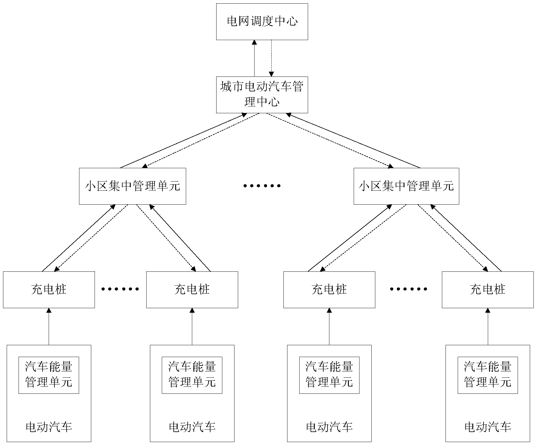
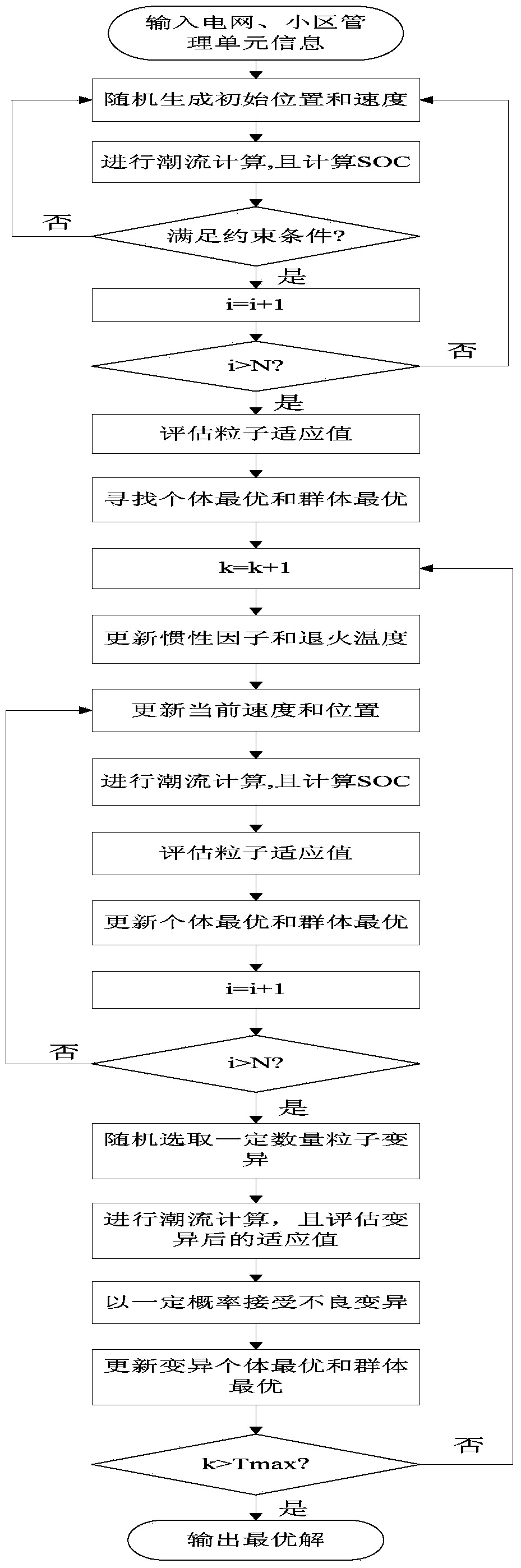
[0061] 1. The present invention includes a vehicle energy management unit, a charging pile, a community centralized management unit, and a power grid dispatching center. The power grid dispatching center regards the centralized management unit of each community as a huge battery, and incorporates it into the unified dispatch of the power grid. The daily load curve is smooth, the network loss is the smallest, the adjustment times of the on-load tap changer are the fewest, and the user satisfaction is high. The objective function is to establish an optimization model with the constraints of safe and stable operation of the power grid, and use the improved particle swarm optimization algorithm to solve the rechargeable capacity of the centralized management unit of each community. The centralized management unit of the community then formulates charging and discharging plans for each vehicle according to the different needs of electric vehicles. , the specific unit functions are a...


PUM


Abstract

The invention discloses a large-scale electric vehicle optimized charging and discharging system and method based on the optimal power flow. The method comprises the steps that a power grid dispatching center enables each cell centralized management unit to be equivalent to a storage battery, the cell centralized management units are brought into unified dispatching of a power grid, an optimization model is built by using a smooth daily load curve, the minimum transmission loss, the minimum number of regulation times of on-load voltage regulating transformers and the highest user satisfaction degree as objective functions and by being restrained and regulated by power grid safe and stable operation behaviors, the charging capacity of each cell centralized management unit is obtained by using the improved particle swarm optimization algorithm, and each cell centralized management unit is used for formulating a charging and discharging plane for each vehicle according to different requirements of electric vehicles. By means of the large-scale electric vehicle optimized charging and discharging system and method, various problems caused because a large number of electric vehicles have access to the power grid to be charged and discharged can be solved, charging and discharging of the electric vehicles are completed in sequence, the requirement of users for electricity consumption can be met, and meanwhile operation safety and economical efficiency of the power grid are improved by making full use of the electric vehicles.

Description

technical field [0001] The invention relates to an optimized charging and discharging system for a large-scale electric vehicle, in particular to an optimal charging and discharging system for a large-scale electric vehicle based on an optimal power flow. Background technique [0002] As a new generation of energy-saving and environment-friendly vehicles, Electric Vehicle (EV) is an inevitable trend in the development of the automobile industry. Electric vehicles have dual identities of controllable load and power source. When charging, they can be regarded as the load of the grid, and when discharging, they can be regarded as the power supply of the grid. Electric vehicles provide opportunities to improve the economic operation of the grid. However, if large-scale electric vehicles are connected to the grid at the same time, their disorderly charging and discharging behavior will bring a strong impact on the grid, which may overload the grid and affect the security and econ...

Claims


Application Information

Patent Timeline
IPC IPC(8): H02J7/00H02J3/28H02J13/00H01M10/44
CPCY04S30/12Y04S30/14Y02E40/70Y02T90/167Y04S10/50Y02E60/10
Inventor 杨军何立夫
Owner WUHAN UNIV
Why Eureka
Try Eureka