
Aircraft fuselage and method for constructing a floor in such a fuselage

A technology for aircraft and fuselage, applied in the field of aircraft fuselage, can solve the problems of installation difficulty and time-consuming, and achieve the effect of good mechanical performance

Active Publication Date: 2014-06-04
AIRBUS OPERATIONS (SAS)
View PDF7 Cites 0 Cited by
  • Summary
  • Abstract
  • Description
  • Claims
  • Application Information

AI Technical Summary

Problems solved by technology

Even though this solution allowed for good booting and good maintenance of the systems 14, the installation of these systems 14 proved to be a difficult and time-consuming operation

Method used


Image

  • Aircraft fuselage and method for constructing a floor in such a fuselage
  • Aircraft fuselage and method for constructing a floor in such a fuselage
  • Aircraft fuselage and method for constructing a floor in such a fuselage

Examples


Embodiment Construction

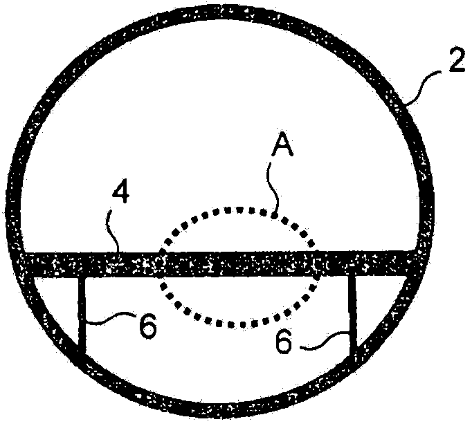
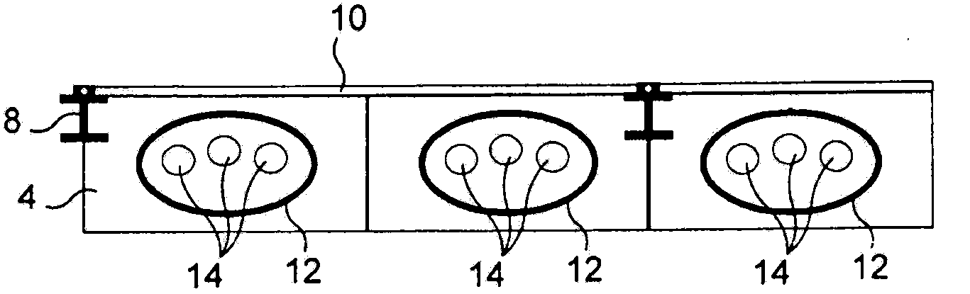
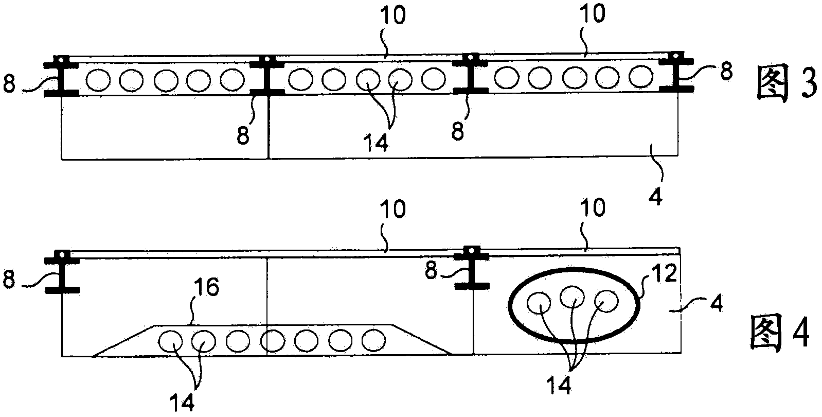
[0039] Figure 1 to Figure 4 already described at the beginning of this document. As mentioned in the beginning, Figure 5 is enlarged figure 1 Detail view of area A of . Should Figure 5 The structure of an aircraft floor according to the invention is shown. The floor comprises beams 104 according to the invention, longitudinal rails 108 and panels 110 of the floor.

[0040] The longitudinal rails 108 will not be described in detail here. In the floor according to the invention, the rails can have the shape of conventional longitudinal rails that are commonly used in aircraft floor structures and are used to accommodate, for example, cabin seats of aircraft. In the embodiment shown here, the longitudinal rail 108 is in the shape of a rail of an I-profile, which is also provided with a groove, which is used in particular to fasten a seat or other elements to the corresponding floor.

[0041] The panels 110 constituting the floor itself are not described again. This can...


PUM


Abstract

Such a fuselage comprises cross-members (104) for constructing a floor, at least one of said cross-members (104) comprising an upper part (124), a lower part (126), means (140-150) for connecting the lower part to the upper part, and at least one opening (152) for the passage of systems (14), said opening being defined between the lower part and the upper part. The upper part (124) of the cross-member is fixed to the fuselage and the dimensions thereof are such that it can withstand the stresses that may be applied to said cross-member when the aircraft is on the ground, and the lower part (126) is fixed to the upper part (124) in such a way as to reinforce it such that, once they are assembled, the upper part (124) and the lower part (126) can withstand the stresses that may be applied to said cross-member (104) when the aircraft is in flight.

Description

technical field [0001] The invention relates to an aircraft fuselage and a method for realizing a floor in such a fuselage. Background technique [0002] Most aircraft have an overall cylindrical fuselage. The fuselage structure comprises substantially circular frames arranged transversely and connected to each other by spars. [0003] In aircraft for transporting passengers, it is expedient to realize a floor for receiving passengers inside the fuselage. In order to realize such a floor, a conventional solution consists in arranging beams in the individual frames of the fuselage structure and implementing the floor on the beams thus arranged. Most often, this floor joins longitudinal rails used to fix the seats for accommodating the passengers and to fix the various elements (partitions, furniture . . . ) used to realize the interior arrangement of the aircraft. [0004] figure 1 A cross-section of an aircraft fuselage is shown very schematically. A circular frame 2 is...

Claims


Application Information

Patent Timeline
IPC IPC(8): B64C1/18
CPCB64C1/18B64C1/061Y10T29/49622
Inventor B·格兰
Owner AIRBUS OPERATIONS (SAS)
Learn More