Combine harvester operating platform and combine harvester with same
What is Al technical title?
Al technical title is built by PatSnap Al team. It summarizes the technical point description of the patent document.
A technology for combine harvesters and consoles, applied in the field of consoles, which can solve problems such as easy water accumulation, aging and deformation of the instrument panel, and lack of instrument panel, and achieve the effects of not being easy to accumulate water, reducing aging, and reducing vibration
Active Publication Date: 2014-06-11
XINGGUANG AGRI MACHINERY
View PDF8 Cites 7 Cited by
Summary
Abstract
Description
Claims
Application Information
AI Technical Summary
This helps you quickly interpret patents by identifying the three key elements:
Problems solved by technology
Method used
Benefits of technology
Problems solved by technology
In the instrument panel in the prior art, the path identification does not adopt the scale form, and there are only warning lights for water temperature, power supply, and oil quantity on the dial, and there is no specific scale value, which makes the observation not clear enough
At the same time, the surface of the dial is made of plastic material, which is easy to be affected by accumulated water. The main operation panel and the instrument panel are on the same plane, which will cause the accumulated water on the main operation panel to flow to the instrument panel when it rains, thus affecting the operator's observation of the instrument panel. In addition, there is no rubber anti-vibration pad on the instrument panel, which is prone to vibration, resulting in poor contact of the line. It also affects the normal use of the combine harvester
Method used
Image
Click on the blue label to locate the original text in one second.
Reading with bidirectional positioning of images and text.
Examples
Embodiment Construction
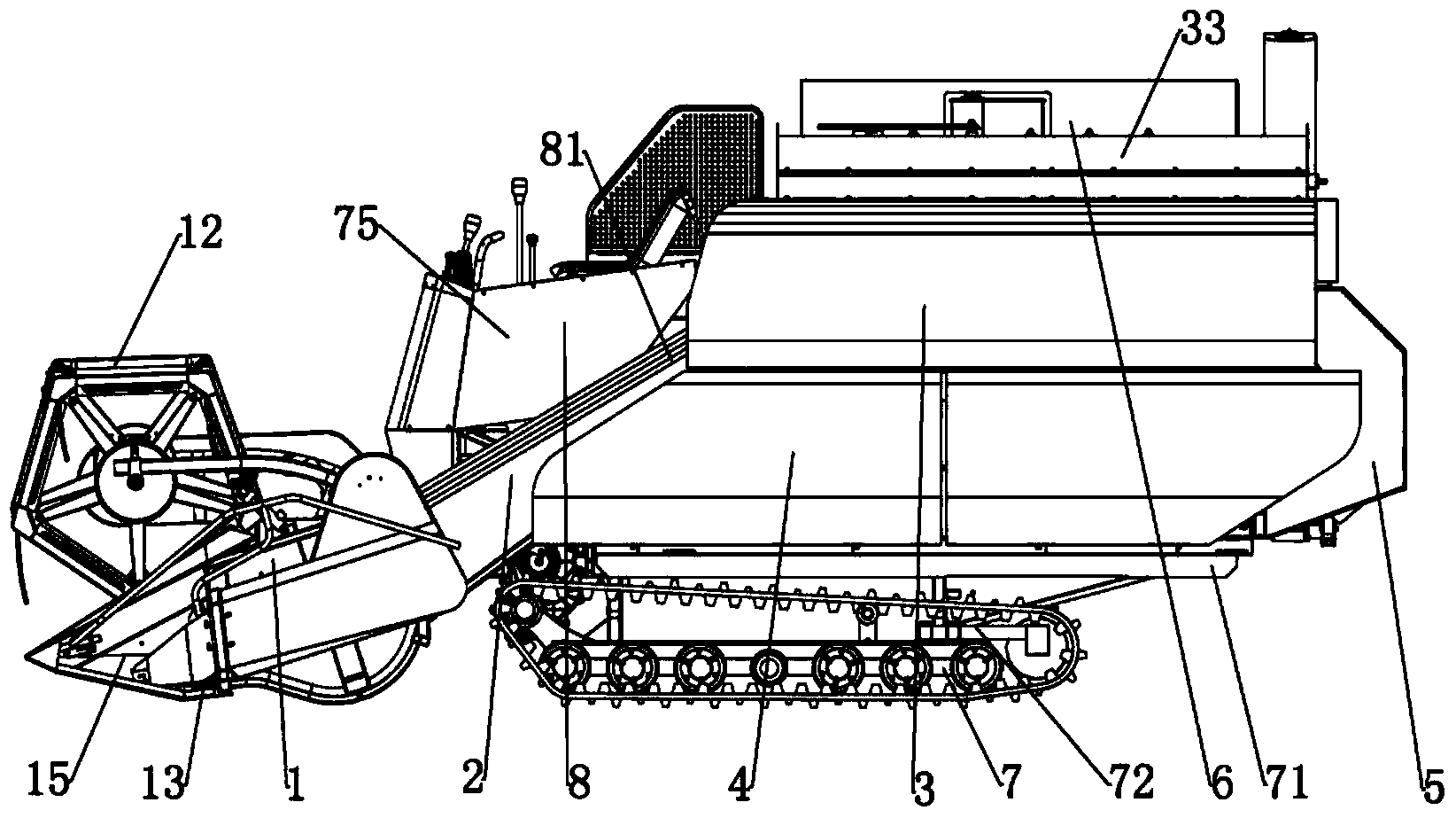
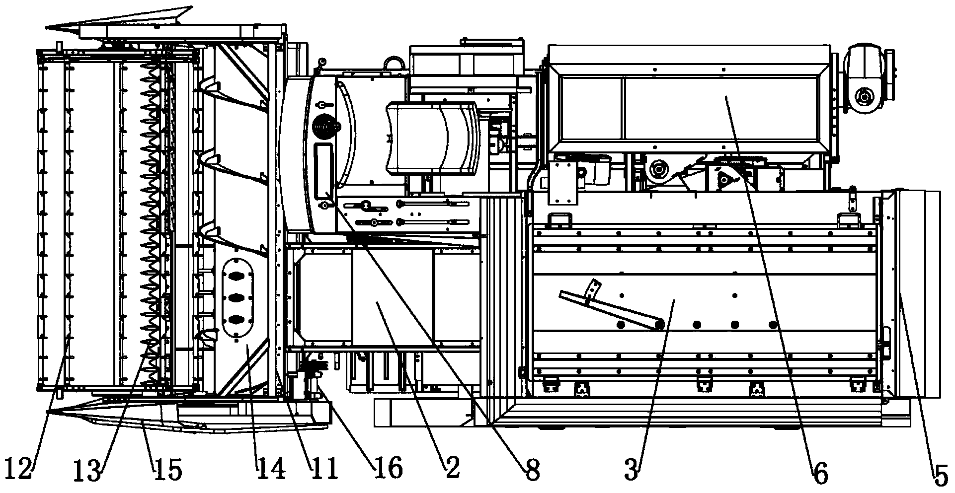
[0029] See attached figure 1 , 2 The combine harvester as a whole can be divided into header 1, feeding and conveying device 2, threshing and separating device 3, grain cleaning device 4, crushing and discharging device 5, grain collecting and unloading device 6, walking device 7 and other auxiliary devices 8 .
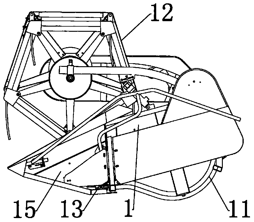
[0030] See attached figure 2 , 3 , the header 1 is used to move crops such as rice and large (small) wheat, and cut off the bottom of the straw, so that the cut crops are poured into the combine harvester, gathered and transported to the feeding port, which mainly includes the header Frame 11, grain reel 12, cutter 13, header auger 14, crop divider 15 and header drive 16, the header frame is used as the main frame of the header to support the various functional components of the entire header, and consists of left and right walls Board, cutting platform bottom plate, knife beam, upper and lower beams, the reel moves rice, large (small) wheat and other crops to th...
PUM
Abstract
The invention relates to a combine harvester operating platform. The combine harvester operating platform comprises a main operation panel, a side operation panel, an instrument panel, a reel lifting rod, a main operating rod, a throttle cable handle, a flameout cable switch, a main speed change lever, a vice speed change lever, a work clutch lever and a grain discharging auger lifting handle, wherein the instrument panel is located in the middle of the main operation panel and comprises an outer frame, a rubber pad, a main screen, an oil pressure path identifier, an engine revolving speed path identifier, a water temperature path identifier, a power supply path identifier, an oil pressure rotating axis, a revolving speed rotating axis, a water temperature rotating axis, a power supply rotating axis, a left turn indicating lamp, a right turn indicating lamp, a power supply indicating lamp, a charge indicating lamp, a valley full warning indicating lamp, a liquid-crystal timer, an oil pressure pointer, a revolving speed pointer, a water temperature pointer and a power supply pointer. The invention relates to a combine harvester with the operating platform. The operating platform provided by the invention is attractive and generous, is good in transparency and difficult in water accumulation and is more beneficial to operator observation.
Description
technical field [0001] The present invention relates to a combine harvester console, in particular to a combine harvester console with an instrument panel and a combine harvester with the console. Background technique [0002] With the progress of society and the development of science and technology, more and more machinery and equipment are applied to agricultural production, and the combine harvester is one of them. The combine harvester can complete the harvesting, threshing, separating the stems, removing debris and other processes of cereal crops at one time, and directly obtain various corresponding finished or semi-finished crops from the field. [0003] The combine harvester is a large and complex comprehensive equipment. It is inevitable for the operator to adjust its operating parameters to obtain better results. In order to intuitively understand the various operating parameters of the combine harvester, most of the combine harvesters are equipped with a console...
Claims
Application Information
Patent Timeline
Application Date:The date an application was filed.
Publication Date:The date a patent or application was officially published.
First Publication Date:The earliest publication date of a patent with the same application number.
Issue Date:Publication date of the patent grant document.
PCT Entry Date:The Entry date of PCT National Phase.
Estimated Expiry Date:The statutory expiry date of a patent right according to the Patent Law, and it is the longest term of protection that the patent right can achieve without the termination of the patent right due to other reasons(Term extension factor has been taken into account ).
Invalid Date:Actual expiry date is based on effective date or publication date of legal transaction data of invalid patent.