Decompression device and vacuum drying device

A technology of a vacuum drying device and a decompression device, which is applied in chemical instruments and methods, cleaning methods and utensils, cleaning methods using liquids, etc., and can solve problems such as the inability to completely prevent gas liquefaction.

Active Publication Date: 2015-10-14
爱阔特(上海)清洗设备制造有限公司
View PDF5 Cites 0 Cited by
  • Summary
  • Abstract
  • Description
  • Claims
  • Application Information

AI Technical Summary

Problems solved by technology

However, when a large amount of gas is sucked in a short period of time after the vacuum drying device is activated, the gas cannot be completely prevented from being liquefied, and there is a danger that the liquid will flow into the vacuum pump afterwards.

Method used


Image

  • Decompression device and vacuum drying device
  • Decompression device and vacuum drying device
  • Decompression device and vacuum drying device

Examples


Embodiment 1

[0034] As a first example, refer to the attached figure 1 ~ attached image 3 , the cleaning and vacuum drying apparatus for vacuum drying the workpiece W after cleaning will be described.

[0035] (1) Configuration of the embodiment.

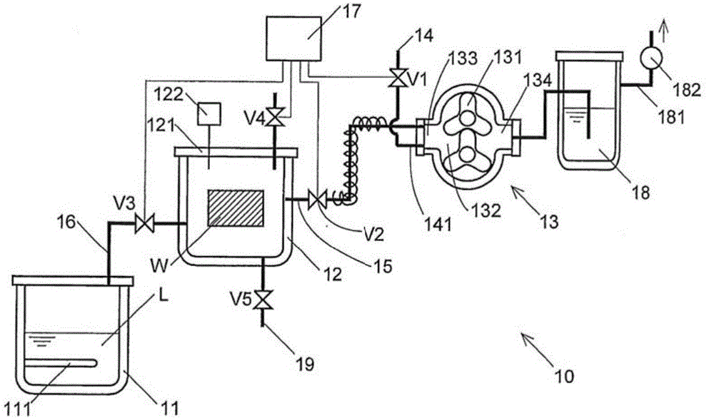
[0036] Such as figure 1 As shown, a cleaning and vacuum drying device 10 includes a liquid storage tank 11 , a sealing tank 12 , a vacuum pump 13 , and an external air inlet 14 .

[0037] The liquid storage tank 11 is a tank body for storing the cleaning liquid used for cleaning the workpiece W. A heater 111 for heating the cleaning liquid is arranged in the liquid storage tank. The heater 111 heats the cleaning liquid in the liquid storage tank. Until the cleaning solution reaches above the vaporization temperature.

[0038] The sealing tank 12 serves as a tank body for accommodating the workpiece W, and has a capacity of 100L. An open cover 121 is provided in the sealed groove for storing and loading and unloading the workpiece W. In or...

Embodiment 2

[0079] Here, the modification of the cleaning and vacuum drying apparatus in the first embodiment will be described.

[0080] In the first embodiment, although the external air introduction pipe 141 is directly connected to the suction port 133 of the vacuum pump 13, like the attached Figure 4 As shown, the external air introduction pipe 141 may be connected to the exhaust pipe 15 (branched from the exhaust pipe 15 ).

[0081] In addition, in the first embodiment, the embodiment of the cleaning and vacuum drying device for cleaning and vacuum drying the workpiece W in the sealing groove 12 has been described. As a modification of the embodiment, it can be configured that only the workpiece W in the sealing groove 12 W carries out the vacuum drying apparatus 10A of vacuum drying (attached Figure 5 ). The vacuum drying device 10A is composed of the cleaning and vacuum drying device except the liquid storage tank 11, the cleaning liquid heater 111, the steam delivery pipeline...

Embodiment 3

[0084] As the pressure reducing device in the present invention, a degassing device for removing gas dissolved in a liquid can be used. use attached Figure 6 The degasser will be described. The structure of the degassing device 10B is the same as that of the above-mentioned vacuum drying device 10A; in use, the difference from the vacuum device 10A is that the degassed liquid L' is injected into the sealing groove 12 instead of the workpiece W. In addition, the operation of the degassing device 10B is the same as that of the vacuum drying device 10A.


PUM


Abstract

The invention discloses a pressure reducing device and a vacuum drying device. The pressure reducing device comprises a seal groove and a vacuum pump connected with the seal groove via a gas exhaust pipe; the gas exhaust pipe is provided with an external gas sucking part; and the external gas sucking part guides the external gas whose flow quantity is smaller than the sucking flow quantity of the vacuum pump into the gas exhaust pipe. According to the invention, by guiding the external gas into the gas exhaust pipe, liquid can be prevented from arriving at the vacuum pump, so performance of the vacuum pump is improved, and faults can be prevented.

Description

technical field [0001] The invention belongs to the technical field of cleaning equipment, and relates to a decompression device for using a vacuum pump to decompress an airtight container, in particular to a part of the gas discharged from the airtight container, which may be liquefied before reaching the vacuum pump. The pressure reducing device used in this case. Such a decompression device can also be applied to a vacuum drying device for drying a liquid-attached object, or a degassing device for removing gas dissolved in a liquid. Background technique [0002] Conventional cleaning equipment is a device that uses a cleaning solution to clean parts and then vacuum-dries them. For example, in the conventional vacuum drying equipment technology, the cleaning and vacuum drying of workpieces are processed in the same processing tank (cleaning tank). In this device, there is a liquid storage tank (steam generating tank) that can store cleaning liquid, and there is a heater ...

Claims


Application Information

Patent Timeline
Patent Type & Authority Patents(China)
IPC IPC(8): B08B3/00B08B13/00
CPCB08B3/04
Inventor 石井郁男
Owner 爱阔特(上海)清洗设备制造有限公司
Why Eureka
Try Eureka