
Commercial vehicles including superstructure and chassis

A technology for commercial vehicles and vehicles, applied to the upper structure, upper structure of trucks, vehicle maintenance, etc., can solve the problems of increased fuel consumption, increased air resistance, and no cleaning effect, so as to reduce fuel consumption and reduce air resistance Effect

Active Publication Date: 2021-01-19
SCANIA CV AB
View PDF1 Cites 0 Cited by
  • Summary
  • Abstract
  • Description
  • Claims
  • Application Information

AI Technical Summary

Problems solved by technology

This results in increased air resistance and therefore increased fuel consumption, and causes the sides of the vehicle to be cleaned by only limited airflow, or airflow through the sides of the vehicle without any cleaning action

Method used


Image

  • Commercial vehicles including superstructure and chassis
  • Commercial vehicles including superstructure and chassis
  • Commercial vehicles including superstructure and chassis

Examples


Embodiment Construction

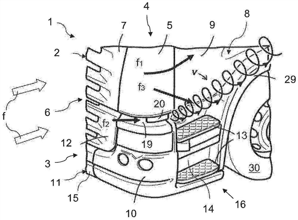
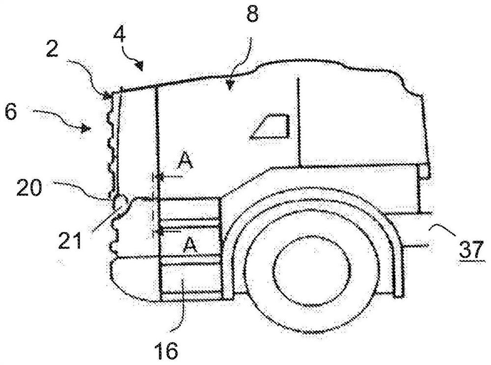
[0024] figure 1 The front of a vehicle 1 is shown, in this case a freight vehicle in the form of a tractor for towing a not shown semi-trailer. The vehicle 1 has an upper structure in the form of a cab 2, the front surface 6 of which faces forward in the direction of movement of the vehicle. The cab is elastically mounted on a frame in the form of the chassis 3 in a manner not depicted in more detail.

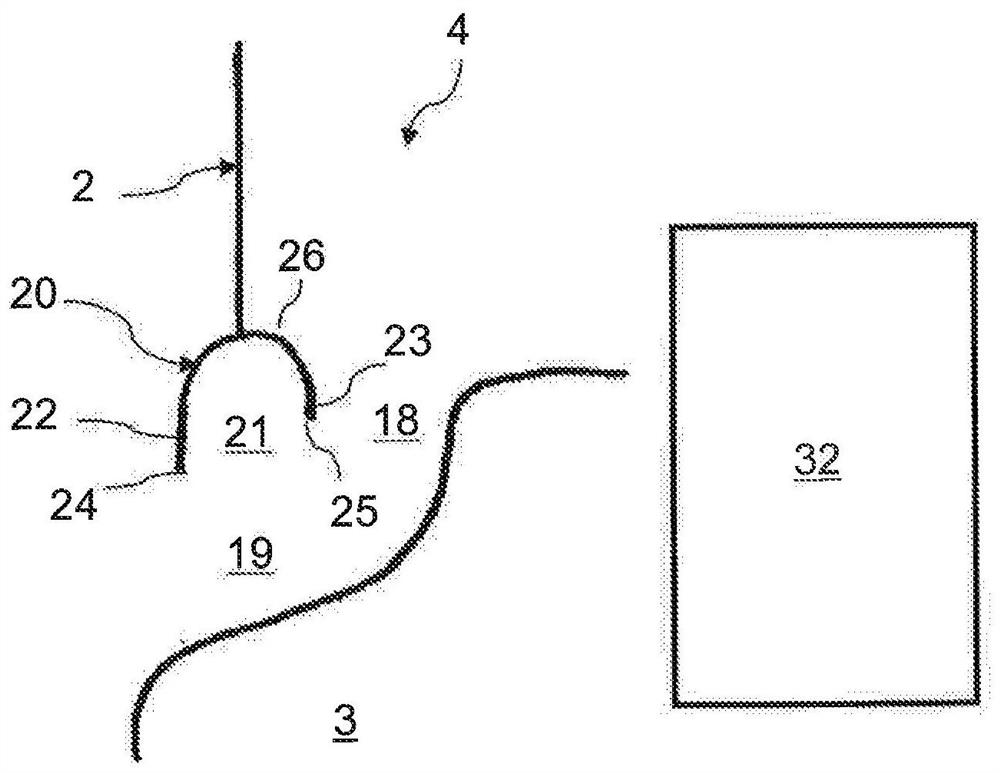
[0025] At least one front corner 4 (only on figure 1 One front corner 4) depicted in , is located on each side of the front surface 6. At the level of the cab 2, each corner 4 takes the form of a curved corner panel 5 situated between an upper front hatch 7 forming part of the front face 6 and a side 8 which Extends rearwardly from the corner in the direction of motion of the vehicle and includes the door 9 . At the level of the chassis 3 , the corner 4 takes the form of a curved portion 10 of a bumper 11 . The upper portion of the curved portion 10 extends between a lower...


PUM


Abstract

On a moving vehicle (1) an air flow (f1) generated by the draught caused by the moving vehicle is guided round the corner section (4) of the vehicle and along the latter's side section (8) in order to reduce the air resistance and cause the side section (8) to be cleaned by an air flow (f1) which counters its fouling from below by spray and dirt particles. The air flow (f) passes also through an engine space in order to cool an engine. The engine space being relatively cramped means that the air flow (f) is subjected to flow resistance and pressure drop. This leads to part of the air flow (f3) leaking from the engine space, e.g. in the region round a boarding stairway (16). The leaking air flow (f3) may weaken and alter the direction of the air flow (f1), thereby reducing the latter's cleaning effect and increasing the air resistance and the fuel consumption. A redirecting means (50) adapted to redirecting the air flow (f3) in a direction such as not to affect the air flow (f1).

Description

technical field [0001] The present invention relates to the field of aerodynamic properties of commercial vehicles, such as trucks and buses, or more specifically, how airflow is directed around the superstructure of the vehicle. The invention also relates to a method suitable for arranging a device for redirecting an air flow in the manufacture of a commercial vehicle. Background technique [0002] The configuration of the front corners of the cab or body of a commercial vehicle greatly affects the vehicle's air resistance and the degree of fouling on the adjacent sides of the cab or body. Known air deflectors designed to reduce air resistance and prevent such fouling typically include curved shields that extend around the corners of the cab or body so that when the vehicle is in motion around the corners and along the sides of the cab or The sides of the body guide the airflow, which is caused by the moving vehicle, in order to reduce air resistance and clean the sides by...

Claims


Application Information

Patent Timeline
Patent Type & Authority Patents(China)
IPC IPC(8): B60K11/08B60S1/66B62D33/06
CPCB60K11/08B60Y2200/14B62D35/001B62D37/02B60S1/66B62D33/0604
Inventor K·诺哈巴
Owner SCANIA CV AB
Learn More