
Pressure-bearing type sealing cartridge used on spraying pipe inside electrothermal film

A technology of electric heating film and sealing sleeve, which is applied in ohmic resistance heating parts, fluid heaters, lighting and heating equipment, etc., can solve problems such as cable short circuit, and achieve the effect of low probability of cable short circuit

Inactive Publication Date: 2015-02-25
深圳格普斯电热技术有限公司
View PDF4 Cites 0 Cited by
  • Summary
  • Abstract
  • Description
  • Claims
  • Application Information

AI Technical Summary

Problems solved by technology

[0005] In practical application, the applicant found that the above-mentioned sealing ring can only prevent the liquid from reaching the opening end of the electrothermal film inner nozzle through the gap between the inner thread and the outer thread. When the pressure in the container is high, the liquid will pass through The gap between the outer wall of the electrothermal film inner nozzle and the inner hole of the outer screw reaches the opening end of the electrothermal inner nozzle, which will also cause a short circuit of the cable, that is to say, the commonly used flat sealing ring is not tightly wrapped. Due to the outer wall of the electrothermal film inner nozzle, the electrothermal inner nozzle can only be used when the pressure in the container is not very high, and cannot be used when the pressure in the container is high

Method used


Image

  • Pressure-bearing type sealing cartridge used on spraying pipe inside electrothermal film
  • Pressure-bearing type sealing cartridge used on spraying pipe inside electrothermal film
  • Pressure-bearing type sealing cartridge used on spraying pipe inside electrothermal film

Examples


Embodiment Construction

[0015] The preferred embodiments of the present invention will be described in detail below in conjunction with the accompanying drawings.

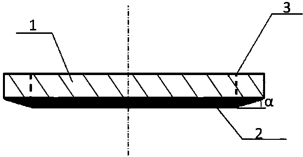
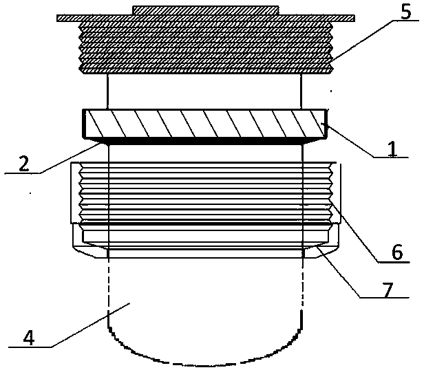
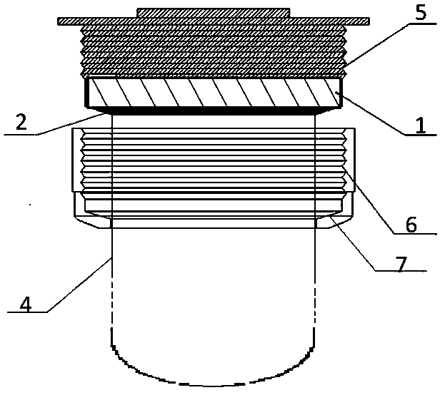
[0016] Such as figure 1 Shown is a schematic diagram of the side structure of the pressure-bearing sealing sleeve in this embodiment. The upper end of the sealing sleeve is a cylinder 1, and the lower end is a round platform 2 with an inclined side. The cylinder 1 and the round platform 2 are coaxially arranged and integrally formed. The radius of the upper bottom surface of the round platform 2 is the same as that of the cylinder 1. The radius of the lower bottom surface is smaller than the radius of the upper bottom surface, the angle α between the inclined side surface and the upper bottom surface or the lower bottom surface is greater than 0° and less than or equal to 60°, and the side of the round table 2 is designed to have a certain angle with the bottom surface. It forms a seal with the internal thread 6 on the container. In add...


PUM


Abstract

The invention relates to the field of accessories of spraying pipes inside electrothermal films, and discloses a pressure-bearing type sealing cartridge used on a spraying pipe inside an electrothermal film. The upper end of the sealing cartridge is a cylinder, and the lower end of the sealing cartridge is a circular truncated cone with the inclined side face. The radius of the lower bottom face of the circular truncated cone is smaller than the radius of the upper bottom face of the circular truncated cone. The radius of the upper bottom face of the circular truncated cone is the same as the radius of the bottom face of the cylinder. The cylinder and the circular truncated cone are coaxially arranged and integrally formed. An inner hole which can be arranged on the outer wall of the spraying pipe inside the electrothermal film in a sleeving mode and tightly attached to the outer wall of the spraying pipe inside the electrothermal film is formed in the position penetrating through the internal centers of the cylinder and the circular truncated cone. Compared with the prior art, when the pressure inside a container is larger, on the one hand, liquid is prevented from reaching the opening end of the spraying pipe inside the electrothermal film along the outer wall of the spraying pipe inside the electrothermal film through a gap between an internal thread and an external thread; on the other hand, the liquid is prevented from reaching the opening end of the spraying pipe inside the electrothermal film along a gap between the outer wall of the spraying pipe inside the electrothermal film and an inner hole of the external thread.

Description

technical field [0001] The invention relates to the field of electrothermal film inner nozzle fittings, in particular to a pressure-bearing sealing sleeve used on the electrothermal film inner nozzle. Background technique [0002] When using the electrothermal film inner nozzle to heat the liquid to be heated in the container, first insert the opening end of the electrothermal film inner nozzle into the inner hole of the outer thread used in conjunction with the opening, and then spray the electrothermal film inside The blind end of the tube passes through the internal thread on the container wall that can be used in conjunction with the above-mentioned external thread, and then the external thread is screwed into the internal thread to fix the inner nozzle tube of the electric heating film on the container wall. At this time, the internal spraying of the electric heating film The blind end of the tube can just be immersed in the liquid to be heated, and finally after the el...

Claims


Application Information

Patent Timeline
Patent Type & Authority Applications(China)
IPC IPC(8): H05B3/02F24H9/18
Inventor 高竹梅郑炯光孔飞
Owner 深圳格普斯电热技术有限公司
Learn More