Sputter deposition device

A film forming device and sputtering technology, which are applied in sputtering plating, ion implantation plating, coating and other directions, can solve problems such as peeling, and achieve the effect of material suppression and preventing the reduction of film forming characteristics

Active Publication Date: 2020-07-14
ULVAC INC
View PDF8 Cites 0 Cited by
  • Summary
  • Abstract
  • Description
  • Claims
  • Application Information

AI Technical Summary

Problems solved by technology

[0006] There is a problem that when sputtered particles adhere to such a non-erosion region of the target, they are peeled off due to abnormal discharge or the like, which causes the generation of particles.

Method used


Image

  • Sputter deposition device
  • Sputter deposition device
  • Sputter deposition device

Examples


Embodiment Construction

[0035] Hereinafter, embodiments of the present invention will be described in detail with reference to the drawings.

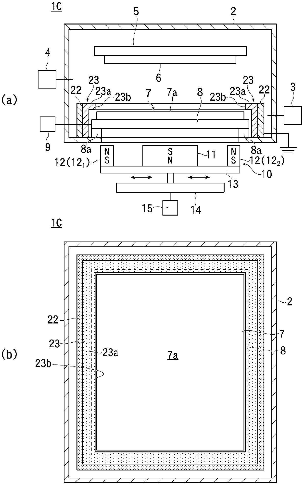
[0036] figure 1 (a) and (b) show the first example of the sputtering film forming apparatus of the present invention, figure 1 (a) is a partial sectional view showing the internal structure, figure 1 (b) is a plan view showing the internal structure of main parts.

[0037] The sputtering film-forming apparatus 1 of this example is a magnetron sputtering system, and has the vacuum chamber 2 set to the ground potential as mentioned later.

[0038] Such as figure 1 As shown in (a), the vacuum chamber 2 is connected to a vacuum exhaust device 3 for evacuating the inside of the vacuum chamber 2 , and is also connected to a sputtering gas that can introduce sputtering gas such as argon (Ar) gas into the vacuum chamber 2 source 4.

[0039] A substrate (film formation object) 6 held by a substrate holder 5 is arranged in the vacuum chamber 2 , and a target 7 atta...


PUM


Abstract

The present invention can suppress the occurrence of an uneroded region at the outer periphery of a sputtering target during film deposition by magnetron sputtering. The present invention is a sputtering deposition device for depositing a film onto a single object for film formation in a vacuum by using a magnetron sputtering method. The present invention has: a magnet device 10 for generating a magnetron beam, which is disposed on the opposite side from a sputtering surface 7a of a single sputtering target 7 and which moves in a direction along the sputtering surface 7a of the sputtering target 7 at the time of discharge; an inner shield section 21 which is disposed around and in close proximity to the outer periphery of the sputtering target 7 and has a floating potential; and an outer shield section 22 which is disposed around the inner shield section 21, has a ground potential, and is made of an electroconductive material.

Description

technical field [0001] The present invention relates to a sputtering device, and particularly relates to the technology of a sputtering film forming device for forming a film by magnetron sputtering. Background technique [0002] Conventionally, in the magnetron sputtering apparatus, there has been a problem that the magnetic field generated on the sputtering target (hereinafter, appropriately referred to as “target”) is changed due to the structure of the magnet apparatus that generates the magnetic field. Therefore, the ions of the sputtering gas are concentrated in the part with higher magnetic flux density, and this part is cut off earlier than the part with lower magnetic flux density. [0003] In order to prevent locally chipped portions (erosion) from occurring in such a target, sputtering has conventionally been performed while moving a magnet device. [0004] However, when sputtering is performed in such a manner, when the plasma captured by the magnetic field of t...

Claims


Application Information

Patent Timeline
Patent Type & Authority Applications(China)
IPC IPC(8): C23C14/35C23C14/34
CPCC23C14/35C23C14/34C23C14/564H01J37/3441
Inventor 阪上弘敏大野哲宏
Owner ULVAC INC
Why Eureka
Try Eureka