Profile stamping device and profile stamping method

A technology for stamping devices and profiles, applied in the field of stamping devices, can solve problems such as low assembly efficiency, operator smashed hands, loud noise, etc., and achieves the effects of improving safety, reducing noise pollution, and preventing deformation.

Active Publication Date: 2014-06-11
OCEANKING DONGGUAN LIGHTING TECH +2
View PDF6 Cites 8 Cited by
  • Summary
  • Abstract
  • Description
  • Claims
  • Application Information

AI Technical Summary

Problems solved by technology

During the beating process, the operator is prone to injuring his hands, and there...

Method used


Image

  • Profile stamping device and profile stamping method
  • Profile stamping device and profile stamping method
  • Profile stamping device and profile stamping method

Examples


Embodiment Construction

[0043] In order to facilitate the understanding of the present invention, the present invention will be described more fully below with reference to the associated drawings. Preferred embodiments of the invention are shown in the accompanying drawings. However, the present invention can be embodied in many different forms and is not limited to the embodiments described herein. On the contrary, the purpose of providing these embodiments is to make the disclosure of the present invention more thorough and comprehensive.

[0044] It should be noted that when an element is referred to as being “fixed” to another element, it can be directly on the other element or there can also be an intervening element. When an element is referred to as being "connected to" another element, it can be directly connected to the other element or intervening elements may also be present. The terms "vertical," "horizontal," "left," "right," and similar expressions are used herein for purposes of ill...


PUM


Abstract

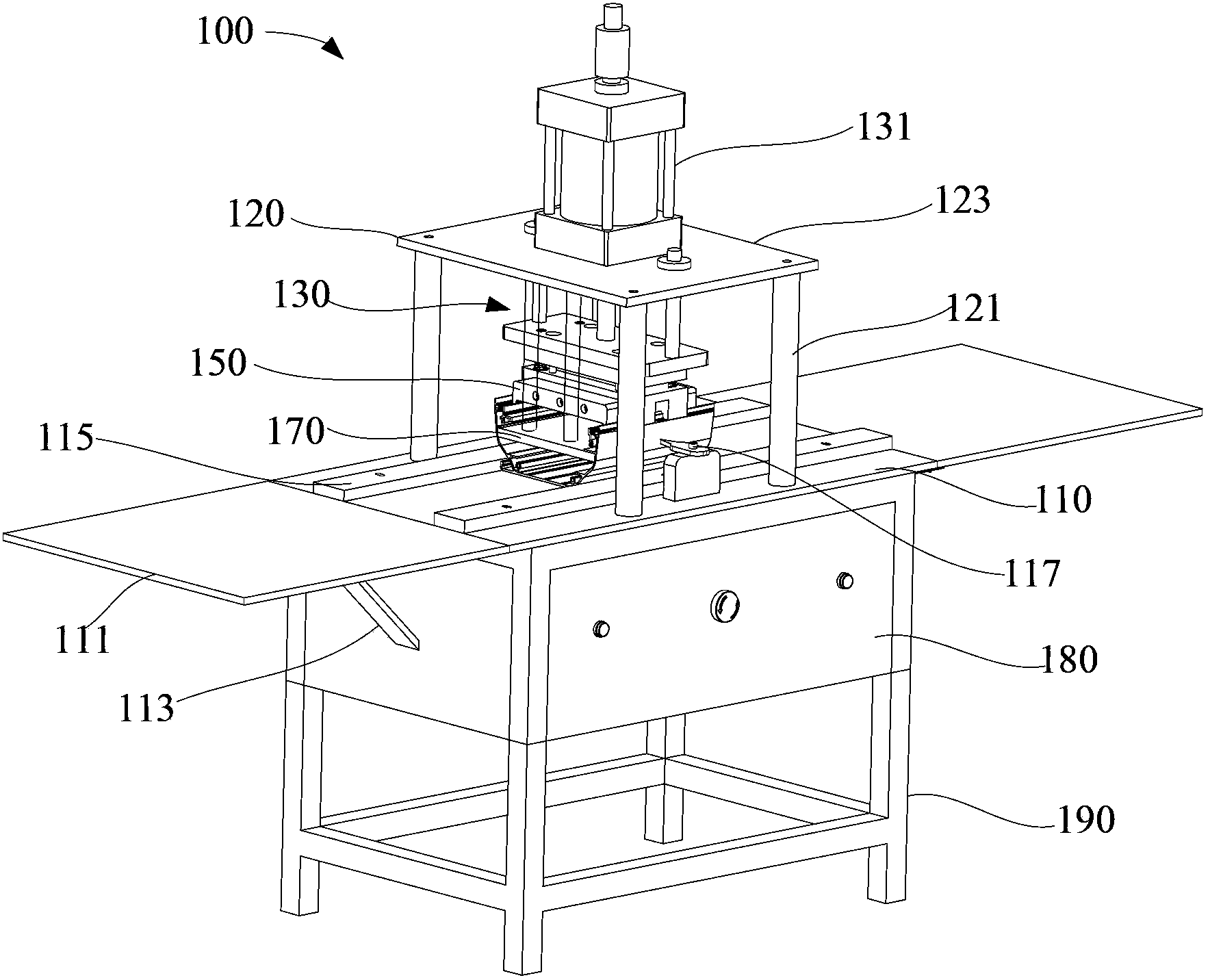
A profile stamping device comprises a carrying platform, a supporting member, a stamping module, elastic members and a first positioning plate. The supporting member comprises a plurality of stand columns and a fixing plate. The stamping module comprises an extensible member, a connecting plate and a punch. The extensible member is fixedly arranged on the fixing plate, and the extensible end of the extensible member is penetratingly arranged on the fixing plate. The connecting plate is arranged between the carrying platform and the fixing plate, and is fixedly connected with the extensible end which drives the connecting plate to move. The punch is fixedly arranged on the connecting plate and is far away from the extensible end. The connecting plate drives the punch to move. One end of each elastic member is fixedly connected with the connecting plate. The first positioning plate is connected with one ends, away from the connecting plate, of the elastic members. The distance between the first positioning plate and a profile is smaller than the distance between the punch and the profile. The first positioning plate moves to enable two ends thereof to be accommodated in guide rails and abutted against the side walls of the profile, and the two ends of the first positioning plates support the two side walls of the profile when the punch punches hooks, so that deformation of the profile is avoided. The invention further provides a profile stamping method.

Description

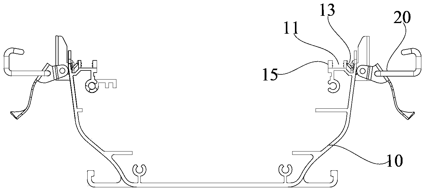
technical field [0001] The invention relates to a stamping device, in particular to a profile stamping device and a profile stamping method. Background technique [0002] At present, the explosion-proof fluorescent lamps used in the petrochemical and oil field industries are made of aluminum alloy profiles. The shell of the explosion-proof fluorescent lamp is fixedly connected with the external support through the hook assembly, and the lamp shell is provided with a slot, and the hook assembly needs to be impacted to be fixed in the slot. Due to the low strength of the shell of the aluminum alloy profile, it is easy to deform during the stamping process. Therefore, usually the hook assembly is assembled on the housing of the lamp by momentary knocking with a hammer to assemble the hook assembly into the slot of the housing. During the beating process, operators are prone to injuring their hands, and there are problems such as high noise and low assembly efficiency during t...

Claims


Application Information

Patent Timeline
IPC IPC(8): B21D39/00B21D43/00B21D37/00
Inventor 周明杰蔺波
Owner OCEANKING DONGGUAN LIGHTING TECH
Why Eureka
Try Eureka