Long and thin cutter support device

A technology for supporting devices and cutting tools, which is used in manufacturing tools, grinding workpiece supports, and other manufacturing equipment/tools, etc., can solve the problems of low tool processing yield, tool bar breakage, and tool bar deformation under compression. , to achieve the effect of improving tool processing quality and yield, reducing the number of feeding times, and improving production efficiency

Inactive Publication Date: 2014-06-11
KUNSHAN YUNCO PRECISION IND TECH
View PDF5 Cites 1 Cited by
  • Summary
  • Abstract
  • Description
  • Claims
  • Application Information

AI Technical Summary

Problems solved by technology

[0003] Both the processing and grinding of transmission tools are carried out in a five-axis linkage precision grinding machine. When processing slender tools in this processing method, there are the following problems: 1. Since the tool bar is in contact with the high-speed rotating grinding wheel at the head during processing , the effect of high speed and force causes the tool bar to vibrate easily, especially the processing of slender tools may even cause the tool bar to deform under pressure. Once the contact angle and feed rate of the grinding wheel and the tool bar deviate, it is extremely It is easy to cause the tool bar to break or the tool edge to break out of the gap, resulting in a large number of waste products, so that the yield of the final tool processing is not high; 2. The tool bar directly passes through the shaft core of the rotating shaft and is clamped at its end On the rotating shaft, a longer length is left at the front end so that multiple tools can be processed in one load, which will inevitably result in a longer distance from the initial processing point to the chuck to hold the tool, which virtually increases the grinding wheel at the processing point. The length of the force arm at which the force is applied, the tool produced in this state is more susceptible to chatter
3. Unable to feed automatically

Method used


Image

  • Long and thin cutter support device
  • Long and thin cutter support device

Examples


Embodiment Construction

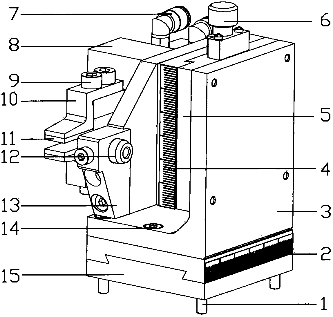
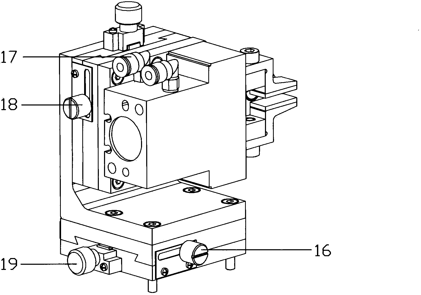
[0009] refer to Figure 1-2 , the specific embodiment adopts the following technical solutions: it includes a manual Y-axis fixing screw 1, a manual Y-axis scale 2, a manual Z-axis mount 3, a manual Z-axis scale 4, a manual Z-axis 5, a manual Z-axis adjustment knob 6, The first cylinder air pipe joint 7, cylinder 8, parallel two-finger clamp fixing screw 9, parallel two-finger clamp 10, rubber pad 11, bushing 12, bushing mounting seat 13, manual Z-axis mounting seat fixing screw 14, manual Y-axis 15, manual Y-axis set screw 16, second cylinder air pipe joint 17, manual Z-axis set screw 18 and manual Y-axis adjustment knob 19, manual Y-axis set screws are arranged below the four corners of manual Y-axis 15 1. A manual Y-axis scale 2 is provided on the side of the manual Y-axis 15, and a manual Y-axis set screw 16 is provided on the opposite side of the manual Y-axis scale 2. On the side adjacent to the manual Y-axis set screw 16 A manual Y-axis adjustment knob 19 is provided, ...


PUM


Abstract

The invention discloses a long and thin cutter support device, and relates to the field of precision cutter machining equipment. The long and thin cutter support device is characterized in that manual Y-axis fixing screws are arranged on the lower sides of four corners of a manual Y-axis, a manual Y-axis scale is arranged at a side edge of the manual Y-axis, a manual Y-axis set screw is arranged on the side, which is opposite to the manual Y-axis scale, of the manual Y-axis, a manual Y-axis adjusting knob is arranged at the side edge, which is adjacent to the manual Y-axis set screw, of the manual Y-axis, a manual Z-axis mounting seat is arranged above the manual Y-axis, a manual Z-axis is connected to the upper side of the manual Z-axis mounting seat by a fixing screw of the manual Z-axis mounting seat, a manual Z-axis scale is arranged on a side of the manual Z-axis, a manual Z-axis set screw is arranged on the side, which is opposite to the manual Z-axis scale, of the manual Z-axis, and a shaft sleeve is mounted on the side of the manual Z-axis via a shaft sleeve mounting seat. The long and thin cutter support device has the advantages that the cutter machining stability can be improved, the cutter machining quality can be enhanced, the cutter machining yield can be increased, the cutter bar loading frequency can be reduced, and the cutter machining and manufacturing efficiency can be improved.

Description

Technical field: [0001] The invention relates to the field of precision tool processing equipment, in particular to a support device for an elongated tool. Background technique: [0002] Tool, as a professional tool for CNC machine tools to process precision parts, its own precision directly determines the precision of the precision parts processed by it. With the rapid development of precision industrial technology, the requirements for machining accuracy of precision parts are gradually increasing. In order to adapt to the rapid development of precision machining technology, the machining accuracy of cutting tools as tools has increasingly become the focus of research in the field of precision manufacturing. Whether it is machining new This is true whether the tool is regrinding a worn tool that has been used for a period of time. [0003] Both the processing and grinding of transmission tools are carried out in a five-axis linkage precision grinding machine. When process...

Claims


Application Information

Patent Timeline
Patent Type & Authority Applications(China)
IPC IPC(8): B24B3/00
CPCB24B3/00B24B41/06
Inventor 夏发平
Owner KUNSHAN YUNCO PRECISION IND TECH
Why Eureka
Try Eureka