Up-walking steam and liquid flow rope-like dyeing machine

A rope-like dyeing machine and steam flow technology are applied in the directions of spray/jet textile material processing, textile material processing equipment configuration, etc., to achieve the effect of good dyeing effect, benefiting the environment and high yield

Inactive Publication Date: 2014-06-11
HANGZHOU INTELLIGENT DYEING FINISHING EQUIP
View PDF5 Cites 1 Cited by
  • Summary
  • Abstract
  • Description
  • Claims
  • Application Information

AI Technical Summary

Problems solved by technology

Because of its own insurmountable defects, it is difficult to popularize: (1) Because the dyeing method is that the dye solution is sprayed onto the surface of the cloth under the action of airflow, the permeability is poor, and it cannot dye high-density fabrics; (2) Because of its Dyeing mainly acts on the surface of the fabric, so it is difficult to guarantee the dyeing permeability. For particularly heavy fabrics, it is easy to produce quality defects such as colored flowers, and the dyeing effect cannot be achieved, and once the dyeing quality problem occurs, it cannot be re-dyeed (repaired); (3) Due to the impact of the steam flow, the dyeing of light and thin cloth (less than 60 grams) will cause disorder, floating, and irregular flying; (4) Due to the needs of the gas flow, its power consumption is higher than that of the existing ones. The power consumption of the liquid flow dyeing machine is more than doubled; (5) due to the structure of the equipment (high fabric lifting height), the tension is high during the dyeing cycle, which is prone to quality defects; Dyeing of dense and light (less than 60g), heavy cloth

Method used


Image

  • Up-walking steam and liquid flow rope-like dyeing machine

Examples


Embodiment Construction

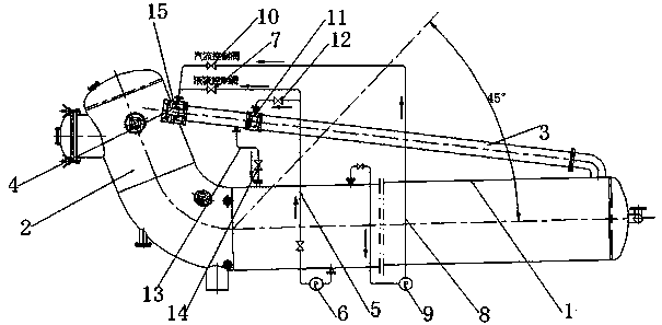
[0017] The installation position of the main cylinder is upturned at the tail end, and the tail end of the main cylinder is at an angle of 0-45° to the front end of the main cylinder. When the cloth enters the nozzle of the cloth guide pipe, the spray dyeing is carried out by the mist steam carrying the dyeing liquid and the cloth is pushed into the cloth guide pipe. After assisting the dyeing and circulation boosting of the cloth, the cloth enters the main cylinder. At this time, the main cylinder with the upturned end is smoothly circulated in the dyeing machine due to the gravity and the action of the dye solution.

[0018] There is an automatic air bag removal device in front of the steam jet nozzle. Our company has applied for a utility model patent (application acceptance number 201320043945.2) - an automatic air bag removal device, which removes and partially removes the air bag and dyeing liquid carried in the cloth dyeing cycle. It is conducive to the deeper penetrati...


PUM


Abstract

The invention relates to an L-shaped up-walking steam and liquid flow rope-like dyeing machine. The L-shaped up-walking steam and liquid flow rope-like dyeing machine comprises a main barrel, a fabric guide head and a fabric guide pipe, wherein a steam flow spray nozzle is arranged at the joint of the fabric guide pipe and the fabric guide head, the steam flow spray nozzle is internally provided with a plurality of atomizing spray nozzles, a liquid flow pipe and a liquid inlet pump are connected to the position of the steam flow spray nozzle in the front of the fabric guide pipe below the main barrel, and a first liquid flow control valve is arranged on the liquid flow pipe; a steam flow pipe and a steam flow fan are connected above the main barrel to extract steam in the main barrel to the position of the steam flow spray nozzle in the front of the fabric guide pipe, and the steam flow pipe is provided with a steam flow control valve; the fabric guide pipe is provided with a plurality of liquid flow spray nozzles, a liquid flow pipe and a liquid inlet pump are connected to the positions of the liquid flow spray nozzles on the fabric guide pipe below the main barrel, and the liquid flow pipe is provided with a second liquid flow control valve; a steam flow returning pipe is arranged below the fabric guide pipe between the steam flow spray nozzle and the liquid flow spray nozzles, and the steam flow returning pipe is provided with a steam flow returning control valve. The dyeing machine performs dyeing and circulation by taking the steam flow as main medium and the liquid flow as complementary medium.

Description

technical field [0001] The invention relates to a cloth dyeing machine, in particular to an upward-moving vapor-liquid flow rope dyeing machine used under high temperature and high pressure, normal temperature and pressure. Background technique [0002] At present, the high-temperature, high-pressure, normal-temperature and normal-pressure liquid flow dyeing machines on the market use the circulating water of the dye liquor to form a dye liquor flow, and under the action of the liquid flow, the cloth is repeatedly cycled to complete the dyeing. A single dyeing and recycling method restricts the efficiency and effect of dyeing, and also limits the space for further reduction of bath ratio, energy consumption and emission reduction. [0003] At present, the high-temperature, high-pressure, normal-temperature and normal-pressure airflow dyeing machines on the market are O-type, which atomize the dye solution under the action of high-speed airflow and spray it circularly on the...

Claims


Application Information

Patent Timeline
Patent Type & Authority Applications(China)
IPC IPC(8): D06B1/02D06B23/20
Inventor 李波
Owner HANGZHOU INTELLIGENT DYEING FINISHING EQUIP
Why Eureka
Try Eureka