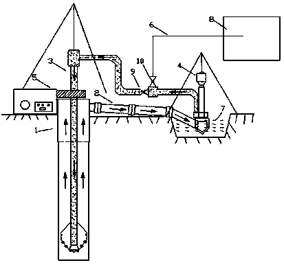
Mud circulating method and circulating system for cast-in-place pile construction
A technology of circulation system and cast-in-place pile, which is applied in earthwork drilling, wellbore/well parts, flushing wellbore, etc. It can solve the problems of untidy site appearance, unusable ground, and unsatisfactory civilized construction, etc., and achieves convenience Construction, significant use effect, clean site effect
- Summary
- Abstract
- Description
- Claims
- Application Information
AI Technical Summary
Problems solved by technology
Method used
Image

Examples
Embodiment 1
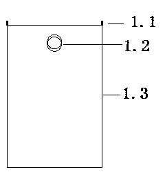
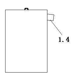
[0017] see figure 2 and image 3 The casing 1 includes a cylinder body 1.3 and a suspension ring 1.1, the cylinder body 1.3 is provided with a slurry port 1.2, and the slurry port 1.2 is connected with a slurry overflow pipe 1.4. The overflow pipe 1.4 and the cylinder body 1.3 are welded upward or downward, and the angle between the overflow pipe 1.4 and the cylinder body 1.3 is set between 70 degrees and 90 degrees. The pipe 1.4 is used for reverse circulation, and the downwardly inclined welded overflow pipe 1.4 is used for positive circulation to ensure smooth circulation of mud.
Embodiment 2
[0019] see Figure 4 and Figure 5 Casing 1 includes a cylinder body 1.3 and a suspension ring 1.1, cylinder body 1.3 is provided with a slurry port 1.2, and the outer wire pup joint 1.5 is welded on the slurry port 1.2 to be connected with the ball end connecting device with a screw thread, and the overflow pipe 1.4 is installed on the ball in the head connector. One end of the overflow pipe 1.4 is a spherical head; the ball head connection device is a tubular body, and the spherical head of the overflow pipe 1.4 is installed in the lumen, and one end of the nozzle is provided with an inner thread buckle to connect with the outer thread nipple 1.5, and the other end of the pipe The inner diameter of the mouth is greater than the outer diameter of the overflow pipe 1.4, so that the pipe body of the overflow pipe 1.4 can be rotated at multiple angles and adjusted freely. The included angle between the upper and lower inclinations of the overflow pipe 1.4 and the cylinder body...
PUM
| Property | Measurement | Unit |
|---|---|---|
| The inside diameter of | aaaaa | aaaaa |
Abstract
Description
Claims
Application Information
 - R&D
- Intellectual Property
- Life Sciences
- Materials
- Tech Scout
- Unparalleled Data Quality
- Higher Quality Content
- 60% Fewer Hallucinations
Browse by: Latest US Patents, China's latest patents, Technical Efficacy Thesaurus, Application Domain, Technology Topic, Popular Technical Reports.
© 2025 PatSnap. All rights reserved.Legal|Privacy policy|Modern Slavery Act Transparency Statement|Sitemap|About US| Contact US: help@patsnap.com