Rotor wheel disc

A technology of rotor wheels and discs, which is applied to the supporting elements of blades, components of pumping devices for elastic fluids, non-variable pumps, etc., and can solve problems affecting the efficiency of steam turbines and gas turbines, blade wear, etc. Achieve the effects of preventing blade tilting, improving service life, and simple and easy operation

Inactive Publication Date: 2014-06-11
SIEMENS AG
View PDF5 Cites 4 Cited by
  • Summary
  • Abstract
  • Description
  • Claims
  • Application Information

AI Technical Summary

Problems solved by technology

This ultimately affects the efficiency of steam and gas turbines and can also cause blade wear

Method used


Image

  • Rotor wheel disc
  • Rotor wheel disc
  • Rotor wheel disc

Examples


Embodiment Construction

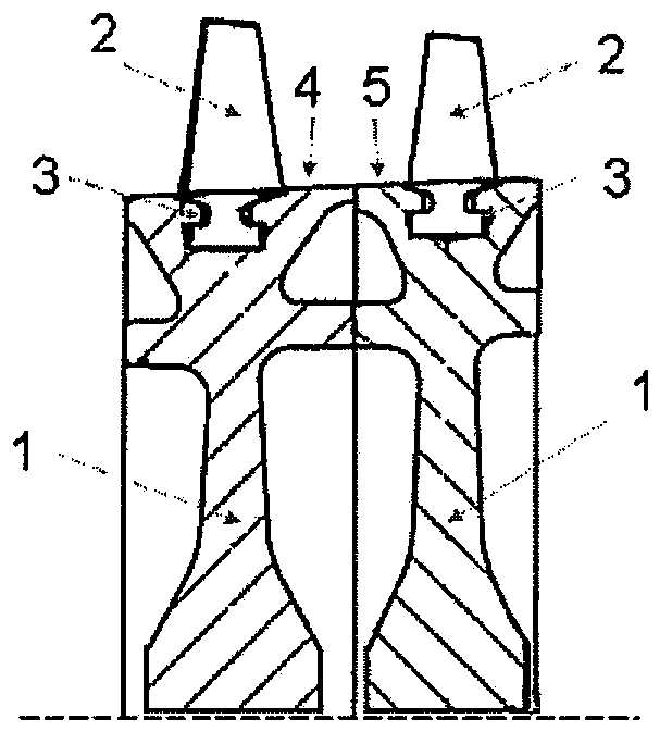
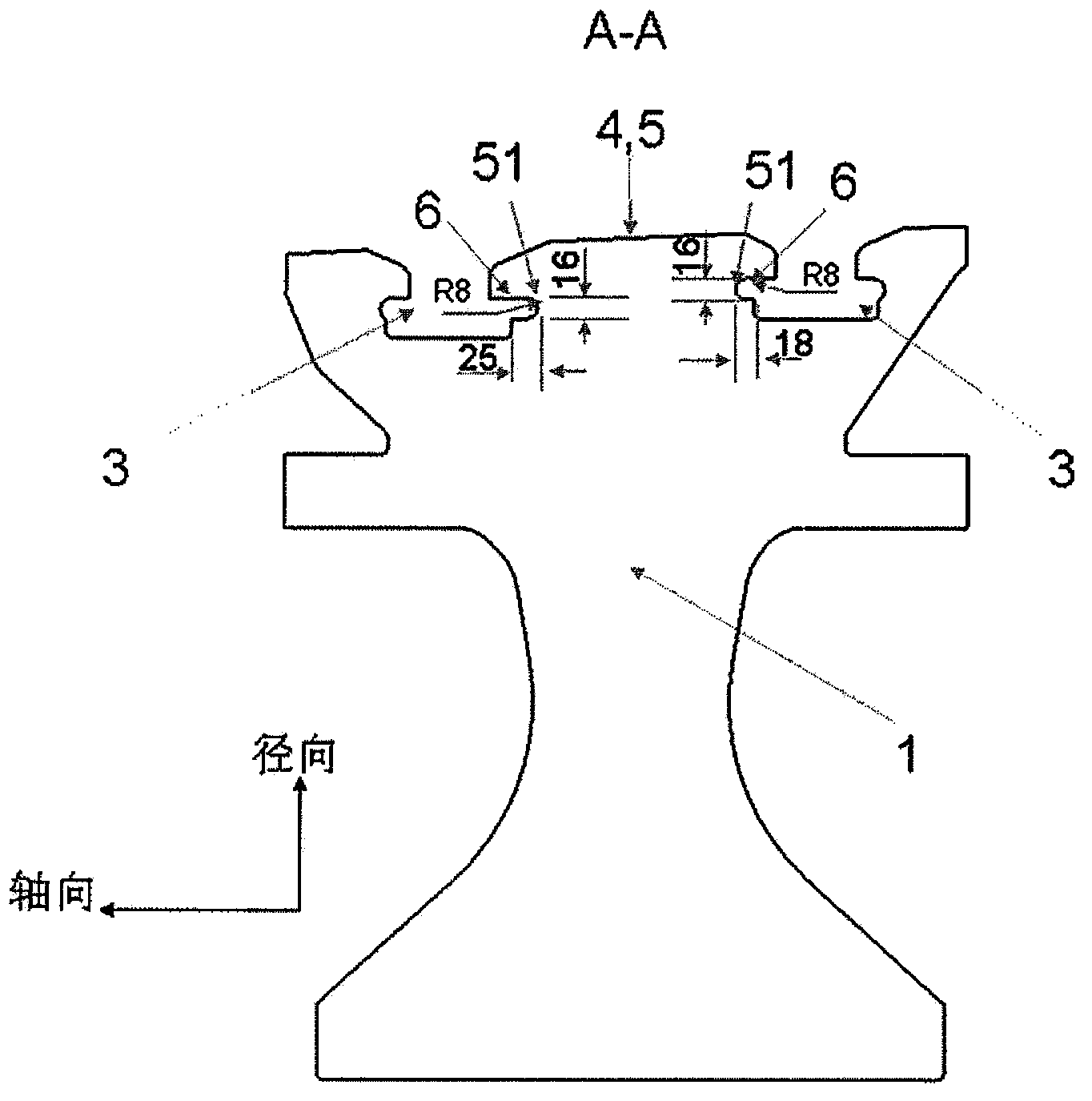
[0017] The reference numerals for the various components in the figures are as follows: rotor disk 1 , blades 2 , root groove 3 , rotor disk parts 4 and 5 , recess 6 , recess chamfer 51 .

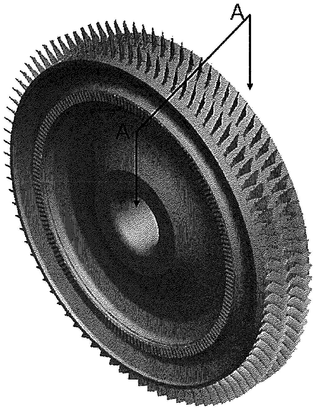
[0018] like figure 2 and 3 As shown, the blades 2 are fixed to the rotor disk 1 by means of the blade root slots 3 . The blade root groove is a T-shaped groove formed by rotary cutting along the circumferential direction of the rotor disk. The blade root groove 3 is provided with a concave portion 6 on the side of the rotor disk with greater rigidity, and the concave portion 6 can penetrate the blade root groove 3 in the circumferential direction of the rotor disk. The concave portion 6 can be machined by cutting with a tool, the tool machining is easy to operate, and the machining cost is low. The concave portion 6 penetrates the blade root groove 3 so that the concave portion and the blade root groove can be processed at the same time, and the inclination of all the blades can be impr...


PUM


Abstract

The invention provides a rotor wheel disc applied to gas turbines and steam turbines. The rotor wheel disc comprises blade root grooves for accommodating blades. Each blade root groove is provided with a recessed portion on one high-stiffness side of the rotor wheel disc. Each recessed portion is used for balancing the stiffness of the rotor wheel disc on two sides of the corresponding blade root groove, so that the blades accommodated in the blade root grooves do not incline due to different stiffness of the two sides of the blade root grooves. Through the recessed portions cut in the blade root grooves, the technical problem of unbalanced stiffness of the rotor wheel disc on two sides of the blades is solved. The recessed portions are simple and easy to process, the stiffness of rotor wheel disc portions on two sides of the blades can be balanced, and stress generated on the rotor wheel disc can be reduced.

Description

technical field [0001] The present invention relates to the field of gas turbines and steam turbines, in particular to rotor discs of the gas turbines and steam turbines. Background technique [0002] like figure 1 As shown, rotor assemblies for steam and gas turbines include a rotor disk and a plurality of rotor blades. During operation, the working fluid can enter from the front side (Upstream) of the rotor disk and flow out from the rear side (downstream) of the rotor disk. The rotor disc is provided with a blade root slot for accommodating the blade root. When steam turbines and gas turbines work, the blades need to rotate at high speed in a high temperature and high pressure environment. In this case, the blades are prone to inclination, and blade inclination is currently a very prominent problem in the field of steam turbines and gas turbines. Vane tilt affects the airflow path, and the clearance between the vane ends and the cylinder. This ultimately affects the ...

Claims


Application Information

Patent Timeline
IPC IPC(8): F01D5/02F04D29/34
Inventor 周叶涛
Owner SIEMENS AG
Why Eureka
Try Eureka