Method and system for detecting dynamic lift range of gag bit of common-rail oil injector

A common rail injector and detection method technology, applied in the field of measurement and control, can solve the problems of low control accuracy, slow response speed, and small control degree of freedom, and achieve high detection accuracy, increased accuracy, and high repeatable measurement accuracy Effect

Active Publication Date: 2014-06-11
BORUN HONGDA (TIANJIN) TECH DEV CO LTD
View PDF5 Cites 3 Cited by
  • Summary
  • Abstract
  • Description
  • Claims
  • Application Information

AI Technical Summary

Problems solved by technology

[0002] With the increasingly strong requirements for low fuel consumption, high power, reduced emissions, and noise of diesel engines, the traditional mechanical diesel fuel injection system composed of a cam mechanism has inherent advantages such as small control freedom, low control precision, and slow response speed. The disadvantages have been unable to meet the requirements

Method used


Image

  • Method and system for detecting dynamic lift range of gag bit of common-rail oil injector
  • Method and system for detecting dynamic lift range of gag bit of common-rail oil injector
  • Method and system for detecting dynamic lift range of gag bit of common-rail oil injector

Examples


Embodiment 1

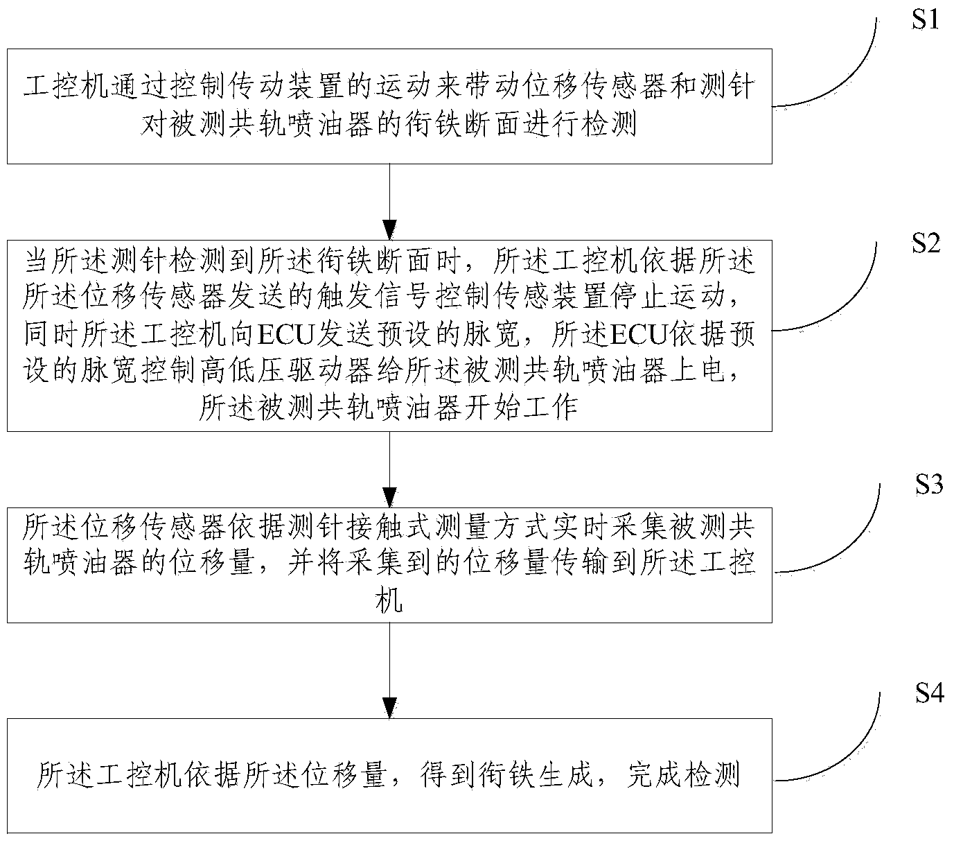
[0033] Such as figure 1 As shown, the embodiment of the present invention provides a method for detecting the dynamic lift of the common rail injector armature, including:

[0034] S1. The industrial computer drives the displacement sensor and the tester to detect the end face of the armature of the common rail injector under test by controlling the movement of the transmission device;

[0035] S2. When the stylus detects the end face of the armature, the industrial computer controls the sensing device to stop moving according to the trigger signal sent by the displacement sensor, and at the same time, the industrial computer sends a preset pulse width to the ECU , the ECU controls the high and low voltage drivers to power on the tested common rail injector according to the preset pulse width, and the tested common rail injector starts to work;

[0036] S3. The displacement sensor collects the displacement of the common rail injector under test in real time according to the s...

Embodiment 2

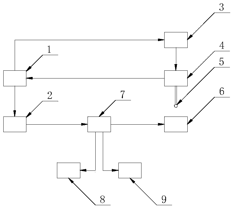
[0047] Such as figure 2 As shown, the embodiment of the present invention also provides a common rail injector armature dynamic lift detection system, including: industrial computer, transmission device, displacement detection device, ECU, high and low voltage driver,

[0048] The displacement detection device includes a displacement sensor and a stylus;

[0049] The high and low pressure drivers are respectively connected with the ECU and the tested common rail injector.

[0050] The industrial computer is respectively connected with the transmission device, the displacement detection device and the ECU, the transmission device is connected with the displacement detection device, and the displacement detection device detects the common rail injector under test.

[0051] Preferably, the device further includes a voltage regulator connected to the high and low voltage drivers for adjusting the driving voltage of the tested common rail injector so as to adapt to common rail in...


PUM


Abstract

The invention provides a method and a system for detecting a dynamic lift range of a gag bit of a common-rail oil injector and relates to the technical field of monitoring. The method comprises the following steps: S1) driving a displacement sensor and a detecting needle to detect an end face of the gag bit of a detected common-rail oil injector by controlling the motion of a driving device through an industrial personal computer; S2) controlling a sensing device to stop running by the industrial personal computer according to a trigger signal sent by the displacement sensor while sending a preset pulse width to an ECU (Electronic Control Unit) by the industrial personal computer, and controlling a high-low pressure driver to electrify the detected common-rail oil injector by the ECU according to the preset pulse width, when the end face of the gag bit is detected by the detecting needle; S3) collecting the displacement of the detected common-rail oil injector in real time by the displacement sensor according to a contact measuring mode of the detecting needle; S4) acquiring the lift range of the gag bit by the industrial personal computer according to the displacement, thereby finishing the detection. According to the method provided by the invention, the detection is performed under a dynamic state, so that the practical running working condition of the gag bit is met and the accuracy is high; the accuracy is higher due to the contact type detection of the detecting needle; the repeated detecting precision is high.

Description

technical field [0001] The invention relates to the technical field of measurement and control, in particular to a method and system for detecting the dynamic lift of an armature of a common rail fuel injector. Background technique [0002] With the increasingly strong requirements for low fuel consumption, high power, reduced emissions, and noise of diesel engines, the traditional mechanical diesel fuel injection system composed of a cam mechanism has inherent advantages such as small control freedom, low control precision, and slow response speed. The disadvantages have been unable to meet the requirements. Therefore, the application of electronic control technology on diesel engines has become inevitable. The electronically controlled high-pressure common rail fuel system not only changes the composition and structure of the traditional mechanical fuel injection system, but also makes the generation of injection pressure completely independent of the engine speed and inj...

Claims


Application Information

Patent Timeline
Patent Type & Authority Applications(China)
IPC IPC(8): F02M65/00
Inventor 不公告发明人
Owner BORUN HONGDA (TIANJIN) TECH DEV CO LTD
Why Eureka
Try Eureka