Collector flowing channel

A heat collector and the first flow channel technology, applied in the field of heat collectors, can solve problems such as water leakage at welding points, unusable water heaters, complex manufacturing process of heat collectors, etc., and achieve the effect of reducing costs and simplifying the manufacturing process

Active Publication Date: 2014-06-11
江苏英泊索尔新能源有限公司
View PDF5 Cites 0 Cited by
  • Summary
  • Abstract
  • Description
  • Claims
  • Application Information

AI Technical Summary

Problems solved by technology

However, in the heat collectors of the above patents, several perforations are first arranged on the stamped main channel, the condensation sleeve is placed in the perforation, and the joint between the condensation sleeve and the main channel is welded and fixed, and then the solar superconducting heat pipe Put it in the condensation sleeve for heating. This connection method will have a defect in practical application, that is, the welding part of the condensation sleeve and the main flow channel will increase or vibrate with the use of time due to the small area of ​​the connection. For other reasons, there will be cracks in the weld and water leakage. Once the collector leaks, the entire water heater will be unusable, and the manufacturing process of this collector is also relatively complicated. It is necessary to make a separate condensation sleeve and weld it.

Method used


Image

  • Collector flowing channel
  • Collector flowing channel
  • Collector flowing channel

Examples


Embodiment Construction

[0019] The present invention will be further described below in conjunction with the examples, but the protection scope of the present invention is not limited only to the examples.

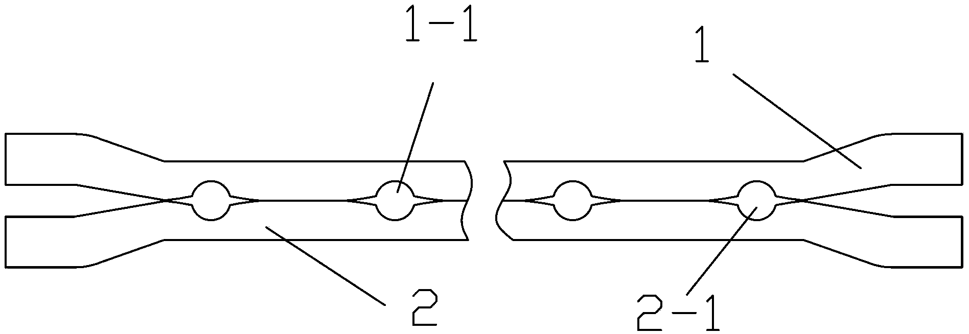
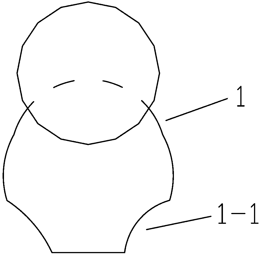
[0020] Such as figure 1 As shown, a heat collector flow channel includes a first flow channel tube 1 and a second flow channel tube 2, one side of the first flow channel tube 1 and one side of the second flow channel tube 2 are connected to each other, and the first flow channel tube 1 is provided with several first grooves 1-1 on the side close to the second flow pipe 2, and the second flow pipe 2 is provided with several second grooves 2-1 on the side close to the first flow pipe 1. 1. The number of the first groove 1-1 is the same as the number and diameter of the second groove 2-1, and the first groove 1-1 and the second groove 2-1 at the corresponding position form a closed space cavity, the first groove 1-1 and the second groove 2-1 are formed by stamping, and the contact part of the first...


PUM


Abstract

The invention discloses a collector flowing channel which comprises a first flowing channel pipe and a second flowing channel pipe. One side of the first flowing channel pipe and one side of the second flowing channel pipe are connected. A plurality of first grooves are formed in one side of the first flowing channel pipe close to the second flowing channel pipe, a plurality of second grooves are formed in one side of the second flowing channel pipe close to the first flowing channel pipe, the number of the first grooves is identical with that of the second grooves, the first grooves and the corresponding second grooves form a closed cavity, and contact portions of the first flowing channel pipe and the second flowing channel pipe are connected in a welding mode. The collector flowing channel has the advantage of effectively solving the problem of water leakage at the welding position of a traditional collector flowing channel and a condensation sleeve. The collector flowing channel is simple in manufacture and low in cost.

Description

technical field [0001] The invention relates to a heat collector of a solar water heater, in particular to a heat collector flow channel. Background technique [0002] With the gradual improvement of people's living standards and the enhancement of awareness of using new energy sources, solar water heaters have been favored by many people and have gradually entered the homes of more ordinary people. Solar water heaters convert sunlight energy into heat energy, and heat water from low temperature to high temperature, so as to meet the hot water use in people's life and production. Solar water heaters are divided into vacuum tube solar water heaters and flat plate solar water heaters according to their structure. At present, vacuum tube solar water heaters are the main ones, accounting for 95% of the domestic market share. Vacuum tube household solar water heaters are composed of heat collectors, water storage tanks, brackets and other related accessories. The conversion of s...

Claims


Application Information

Patent Timeline
Patent Type & Authority Applications(China)
IPC IPC(8): F24J2/46
CPCY02E10/40
Inventor 丁国成
Owner 江苏英泊索尔新能源有限公司
Why Eureka
Try Eureka