

Efficient heat exchange system
A heat exchange system and high-efficiency technology, which is applied in the field of air-conditioning heat exchange, can solve the problems of high heat exchange efficiency, and achieve the effects of improving heat exchange efficiency, improving supercooling, and compact structure
- Summary
- Abstract
- Description
- Claims
- Application Information
AI Technical Summary
Problems solved by technology
Method used
Image

Examples
Embodiment 1
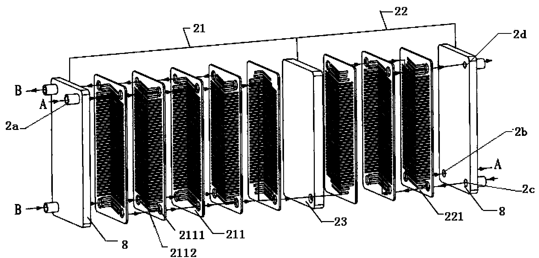
[0037] Such as figure 2 As shown, this embodiment provides a high-efficiency condenser 2 for an air-conditioning heat exchange system. The condenser 2 is a plate condenser and includes a condensation zone 21. The condensation zone 21 is tightly closed by a plurality of condensation heat exchange fins 211 connected to realize the heat exchange between the refrigerant medium A and the cooling liquid B from the compressor 1; the supercooling zone 22, the supercooling zone 22 is formed by a plurality of supercooling heat exchanging fins 221 closely connected, the The supercooling zone 22 is used to realize the heat exchange between the refrigerant medium A after passing through the condensation zone 21 and the refrigerant medium A throttled by the electronic expansion valve 3, and the condensation zone 21 and the supercooling zone 22 pass through a supercooling zone 22. Cold deflector 23 isolation (see Figure 4 ), the supercooling deflector 23 is provided with a supercooling gu...
Embodiment 2
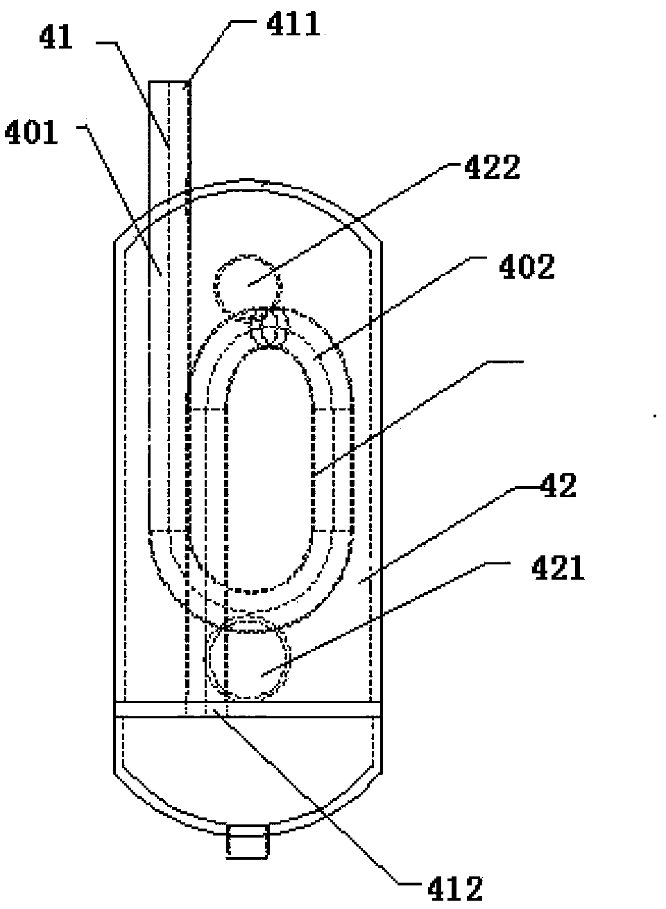
[0046] Such as image 3 As shown, this embodiment provides a cylindrical heat exchanger 4 used in an air-conditioning heat exchange system. The cylindrical heat exchanger 4 has an inner pipe 41 and an outer pipe 42. The inlet 411 of the inner pipe 41 is connected to the The condensation zone 21 is communicated, the outlet 412 of the inner pipe 41 is communicated with the first electronic expansion valve 5, the inlet 421 of the outer pipe 42 is communicated with the second outlet 6d of the superheated area of the evaporator 6, and the outer pipe 42 The outflow port 422 of the compressor 1 communicates with the compressor 1 , and the cartridge heat exchanger is used to realize the heat exchange between the liquid refrigerant A from the condenser 21 and the gas refrigerant A from the evaporator 6 .
[0047] In order to improve the heat exchange uniformity of the cartridge heat exchanger, in this embodiment, the inner pipe 41 has at least two straight pipe sections 401 and an el...
Embodiment 3
[0049] This embodiment provides a high-efficiency heat exchange system, and the high-efficiency heat exchange system adopts the condenser and the cartridge heat exchanger disclosed in Embodiment 1 and Embodiment 2.
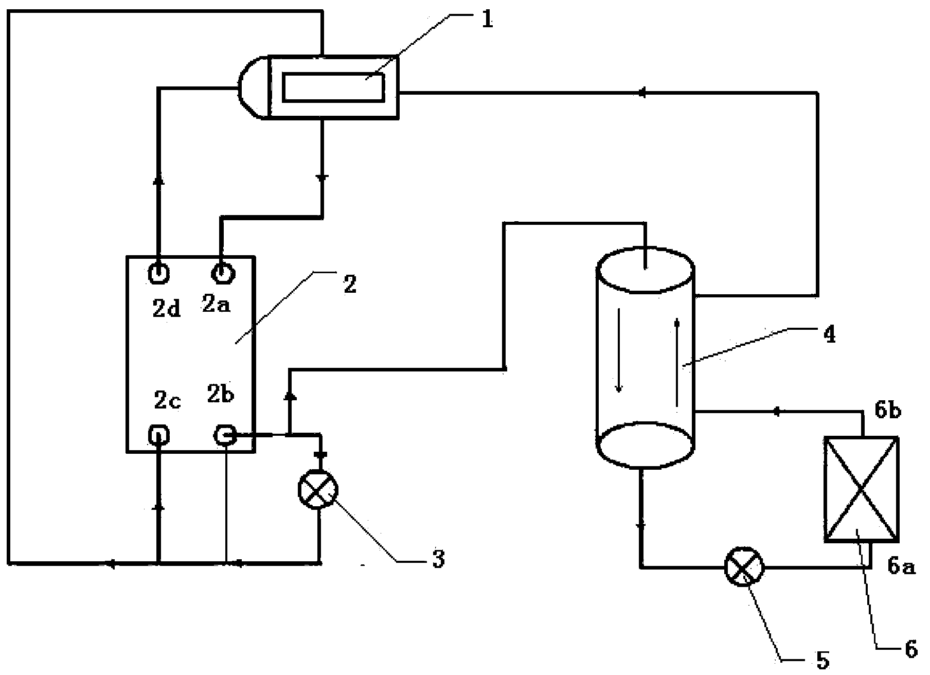
[0050] Such as figure 1 As shown, the specific structure of the high-efficiency heat exchange system includes: a compressor 1, which is used to provide a refrigerant medium A; a condenser 2 (see figure 2 ), the condenser 2 has a condensation zone 21 and a subcooling zone 22 communicating with the condensation zone 21, the condensation zone 21 communicates with the refrigerant medium outlet of the compressor 1, and is used to realize the cooling medium A The heat exchange with the cooling liquid B, the subcooling zone 22 is used to realize the condensation of the refrigerant medium A passing through the condensation zone 21 and throttling through the electronic expansion valve 3 and the condensation zone 21 without electronic expansion The heat exchange between t...
PUM
 Abstract
Description
Claims
Application Information