Projecting apparatus and converging module

A projection device and concentrating module technology, applied in the direction of concentrating mirrors, projection devices, lighting devices, etc., to achieve the effect of reducing the overall volume, reducing optical path difference, and simple structure

Active Publication Date: 2014-06-11
YOUNG OPTICS
View PDF10 Cites 9 Cited by
  • Summary
  • Abstract
  • Description
  • Claims
  • Application Information

AI Technical Summary

Problems solved by technology

As a result, known projection devices often require a

Method used


Image

  • Projecting apparatus and converging module
  • Projecting apparatus and converging module
  • Projecting apparatus and converging module

Examples


Embodiment Construction

[0085] The aforementioned and other technical contents, features and effects of the present invention will be clearly presented in the following detailed description of a preferred embodiment with reference to the drawings. The directional terms mentioned in the following embodiments, such as: up, down, left, right, front or back, etc., are only directions referring to the attached drawings. Accordingly, the directional terms are used to illustrate and not to limit the invention.

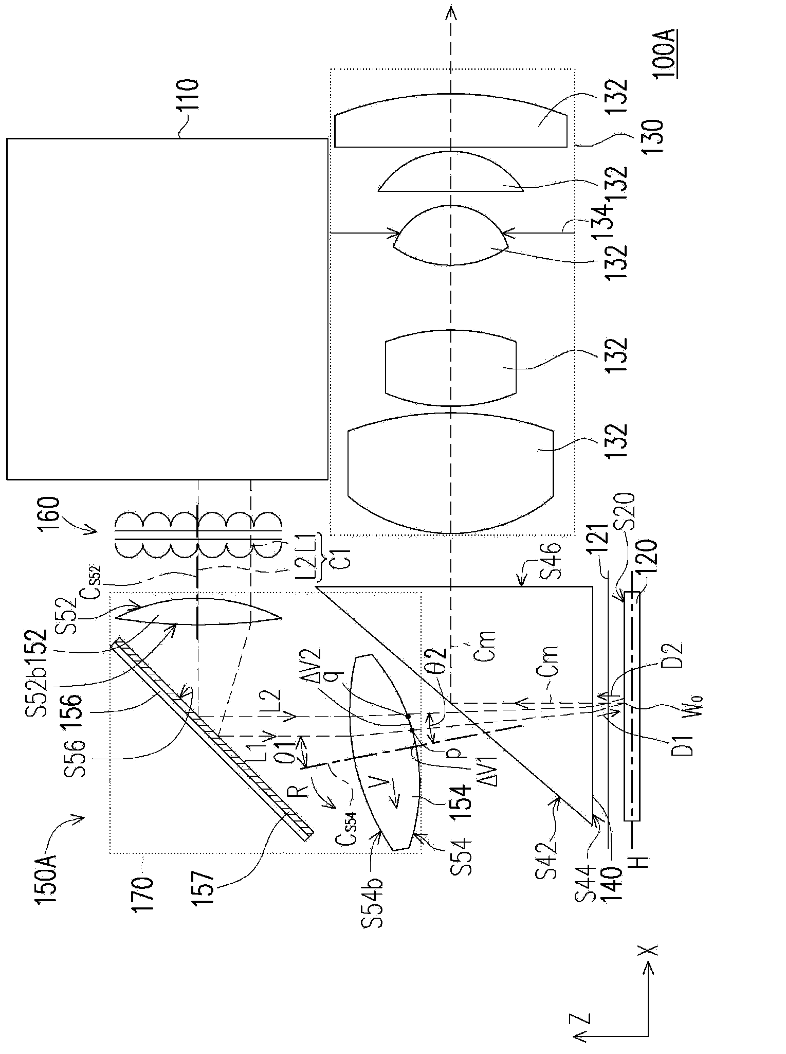
[0086] Figure 1A It is a schematic diagram of a projection device according to an embodiment of the present invention. The projection device 100A of this embodiment includes a light source module 110 , a light valve 120 , a projection lens 130 , a total internal reflection prism (TIR prism) 140 and a light concentrating module 150A.

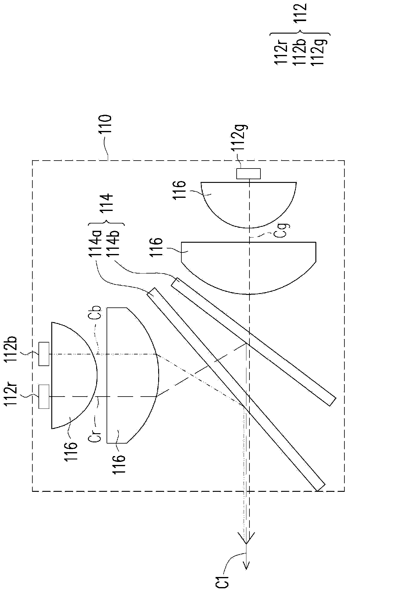
[0087] The light source module 110 is used for providing an illumination beam C1. Figure 1B It is a schematic diagram of a light source module 110 according to an ...


PUM


Abstract

The invention discloses a projecting apparatus and a converging module. The converging module is used for converging and refracting an incident beam and comprises a bent incidence surface, a bent emergence surface and a reflection surface, wherein the bent incidence surface is used for receiving the incident beam, the bent emergence surface is arranged on a transmission path of the incident beam from the bent incidence surface, the reflection surface is arranged on the transmission path of the incident beam and located between the bent incidence surface and the bent emergence surface, and a piece of light in the incident beam passes through the bent incidence surface along the optical axis of the bent incidence surface and emerges from the bent emergence surface in the direction inclining relative to the optical axis of the bent emergence surface. The overall size of the projecting apparatus can be easily reduced, and the converging module has the effect of compensating for optical distances.

Description

technical field [0001] The invention relates to a display device and an optical element, and in particular to a projection device and a light concentrating module. Background technique [0002] Generally speaking, when the projection device performs image projection, the light valve converts the illumination beam into an image beam and reflects the image beam to the projection lens, and then projects the image beam onto the screen through the projection lens to form an image. [0003] In order to make the illumination beam emitted by the light-emitting element enter the light valve uniformly, in the known technology, a plurality of prisms are arranged before the illumination beam enters the light valve, so as to average the light path of the light irradiated at different positions of the prism to enter the light valve. In addition, gaps are reserved between the prisms to generate a total reflection effect, so that the image beams from the light valve can pass through the pri...

Claims


Application Information

Patent Timeline
IPC IPC(8): G03B21/00G03B21/20G03B21/14G02B19/00G02B17/00G02B26/08
CPCH04N1/00G03B21/28F21V13/04G03B21/008G03B21/2066H04N9/3111
Inventor 郑泓祐林裕修陈佑柏陈时伟
Owner YOUNG OPTICS
Why Eureka
Try Eureka