Magnetic passive element and manufacturing method thereof

A technology of magnetic passive components and manufacturing methods, applied in magnetic core manufacturing, inductance/transformer/magnet manufacturing, electrical components, etc., can solve the problems of high cost, decreased inductance value, and high cost of human resources, and achieve outstanding effects and manufacturing costs. reduced effect

Inactive Publication Date: 2014-06-11
DELTA ELECTRONICS CHEN ZHOU
View PDF6 Cites 9 Cited by
  • Summary
  • Abstract
  • Description
  • Claims
  • Application Information

AI Technical Summary

Problems solved by technology

[0002] The magnetic passive components in the prior art usually use flat enameled wires to surround them into a certain shape, and then assemble them with a magnetic material core of a certain shape to form one or more electrical loops; or wire 10 (which can be a single wire or more than two Stranded wire) is directly wound around the magnetic material 20 to form one or more electrical loops, and the end of the wire 10 is connected to the corner tail 30, see figure 1 , figure 1 It is a schematic diagram of the structure of a magnetic passive component in the prior art. The disadvantage of this magnetic passive component is manual winding, high cost of human resources, and low efficiency.
The patent publication number is US2011 / 0108317, and the US patent application titled "PACKAGED STRUCTURE HAVING MAGNETIC COMPONENT AND METHOD THEREOF" discloses a magnetic passive component. The way of wiring forms one or more electrical loops around the magnetic material core. This kind of magnetic passive component manufacturing method is easy to cause the inductance value to drop, and the cost is relatively high for making larger inductors.

Method used


Image

  • Magnetic passive element and manufacturing method thereof
  • Magnetic passive element and manufacturing method thereof
  • Magnetic passive element and manufacturing method thereof

Examples


Embodiment Construction

[0038] Below in conjunction with accompanying drawing, structural principle and working principle of the present invention are specifically described:

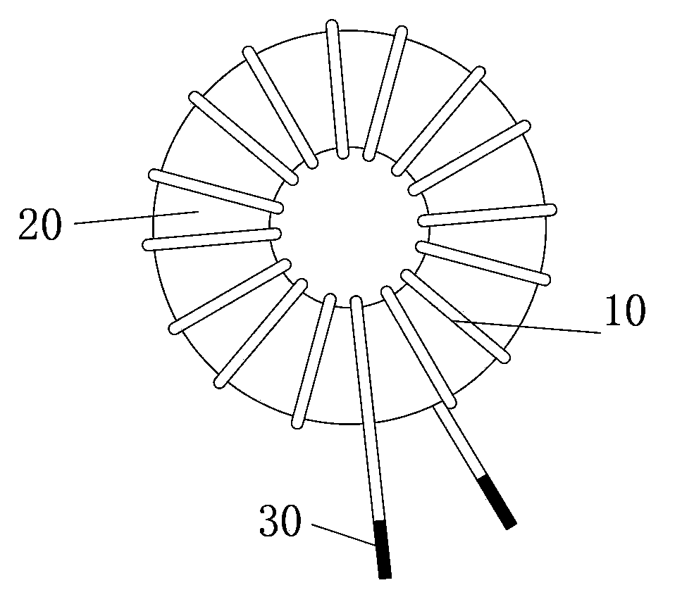
[0039] The magnetic passive element of the present invention is mainly aimed at a magnetic passive element with a large number of coil turns, or a magnetic passive element with a large inductance. The application range of the magnetic passive component is also relatively wide. It can be used not only on the PCB board, but also in high-frequency signal transmission technology or low-frequency power supply, inductors, and transformers.

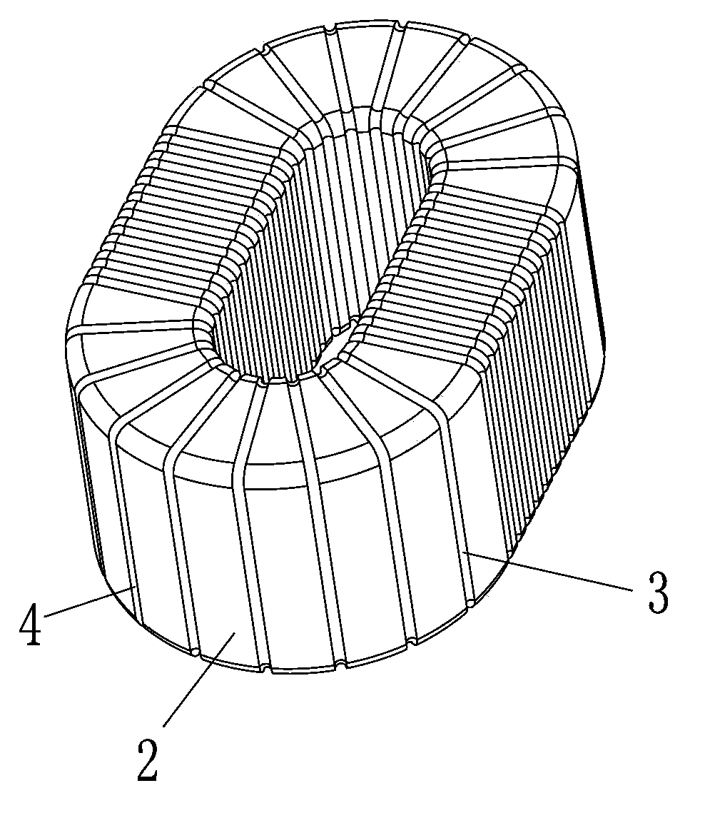
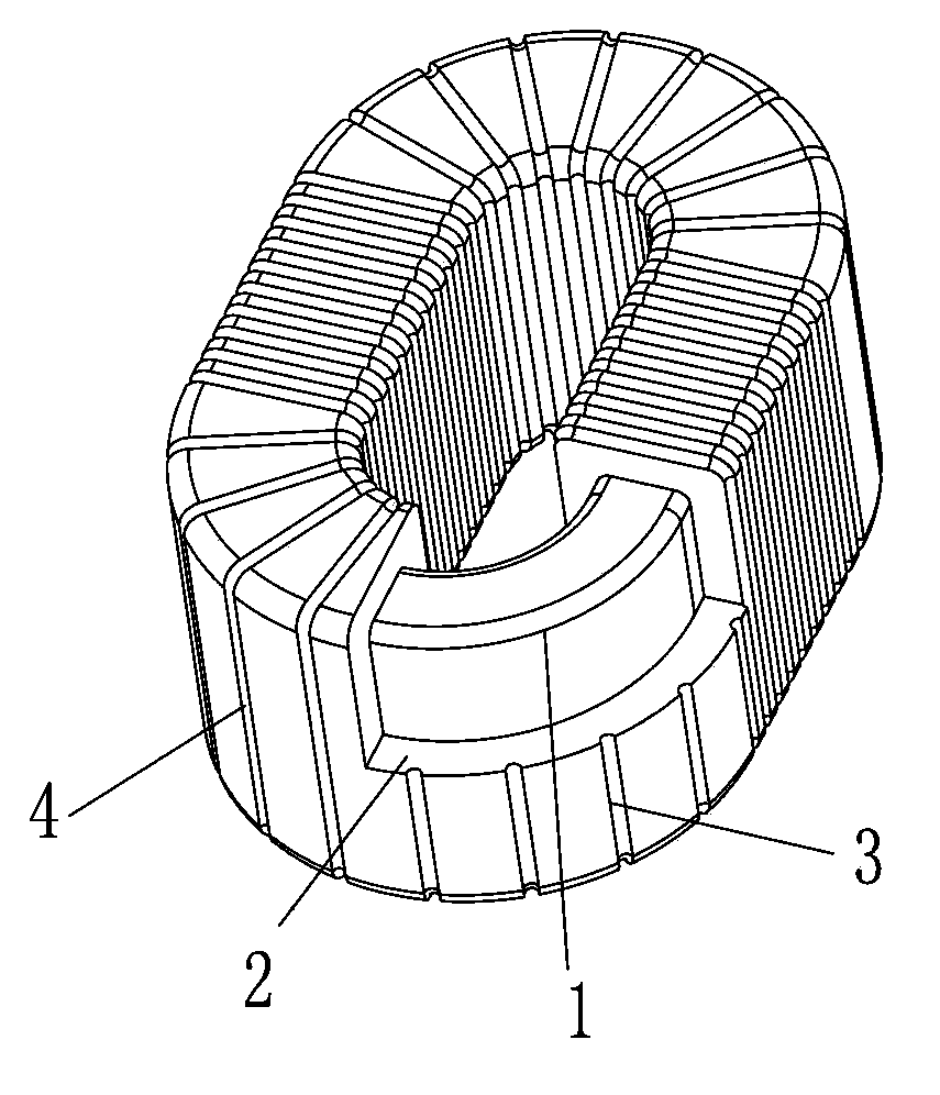
[0040] see Figure 2A ~ Figure 2B , Figure 2A It is a structural schematic diagram of an embodiment of the magnetic passive element of the present invention, Figure 2B for Figure 2A cutaway view. In this embodiment, the magnetic passive element of the present invention includes a magnetic core 1, an insulating layer 2 covering the magnetic core 1, and a metal wire layer 4 deposited on the...


PUM


Abstract

The invention provides a magnetic passive element and a manufacturing method thereof. The magnetic passive element comprises a magnetic core and a metal wire layer twined and covered at the outer surface of the magnetic core; an insulating layer is arranged between the magnetic core and the metal wire layer, and the insulating layer is an insulating material layer including metal ions and is tightly covered on the outer surface of the magnetic core; the insulating layer is provided with one or a plurality of communicated metal ion guide paths covered at the outer surface of the insulating layer, wherein the metal ion guide paths are spiral and can form one or a plurality of electrical loops. The manufacturing method of the magnetic passive element comprises the following steps of setting the magnetic core; directly molding the insulating material layer including the metal ions on the magnetic core by using a die; molding the spiral metal ion guide paths on the surface of the insulating layer; depositing the metal wire layer on the surfaces of the metal ion guide paths to finally form the metal winding on the surface of the magnetic core. The magnetic passive element and the manufacturing method thereof provided by the invention have the advantages of simple process, low production cost and capability of realizing the automatic production with the stable and reliable quality.

Description

technical field [0001] The invention relates to a magnetic passive element and a manufacturing method thereof, in particular to a magnetic passive element and a manufacturing method thereof with a simple process that can realize automatic production. Background technique [0002] The magnetic passive components in the prior art usually use flat enameled wires to surround them into a certain shape, and then assemble them with a magnetic material core of a certain shape to form one or more electrical loops; or wire 10 (which can be a single wire or more than two Stranded wire) is directly wound around the magnetic material 20 to form one or more electrical loops, and the end of the wire 10 is connected to the corner tail 30, see figure 1 , figure 1 It is a structural schematic diagram of a magnetic passive element in the prior art. The disadvantage of this magnetic passive element is manual winding, high cost of human resources, and low efficiency. The patent publication num...

Claims


Application Information

Patent Timeline
Patent Type & Authority Applications(China)
IPC IPC(8): H01F17/06H01F27/30H01F27/32H01F41/00
CPCH01F41/0206H01F27/24H01F5/00H01F17/0033Y10T29/49009
Inventor 杨肇威何汪军陈雪峰许昌潘锦彰谢铭恩
Owner DELTA ELECTRONICS CHEN ZHOU
Why Eureka
Try Eureka