
Micro-dynamic accurate regulation control system and method

A regulation control, micro-power technology, applied in generators/motors, piezoelectric effect/electrostrictive or magnetostrictive motors, electrical components, etc. achieve the effect of isolating interference

Inactive Publication Date: 2014-06-11
ZHEJIANG UNIVERSITY OF SCIENCE AND TECHNOLOGY +1
View PDF6 Cites 5 Cited by
  • Summary
  • Abstract
  • Description
  • Claims
  • Application Information

AI Technical Summary

Problems solved by technology

At present, there are no reports of micro-dynamic components in this area in China, and there is no micro-force precise adjustment method for micro-dynamic components based on the coupling of giant magnetostrictive materials and piezoelectric ceramic materials.

Method used


Image

  • Micro-dynamic accurate regulation control system and method
  • Micro-dynamic accurate regulation control system and method
  • Micro-dynamic accurate regulation control system and method

Examples


Embodiment 1

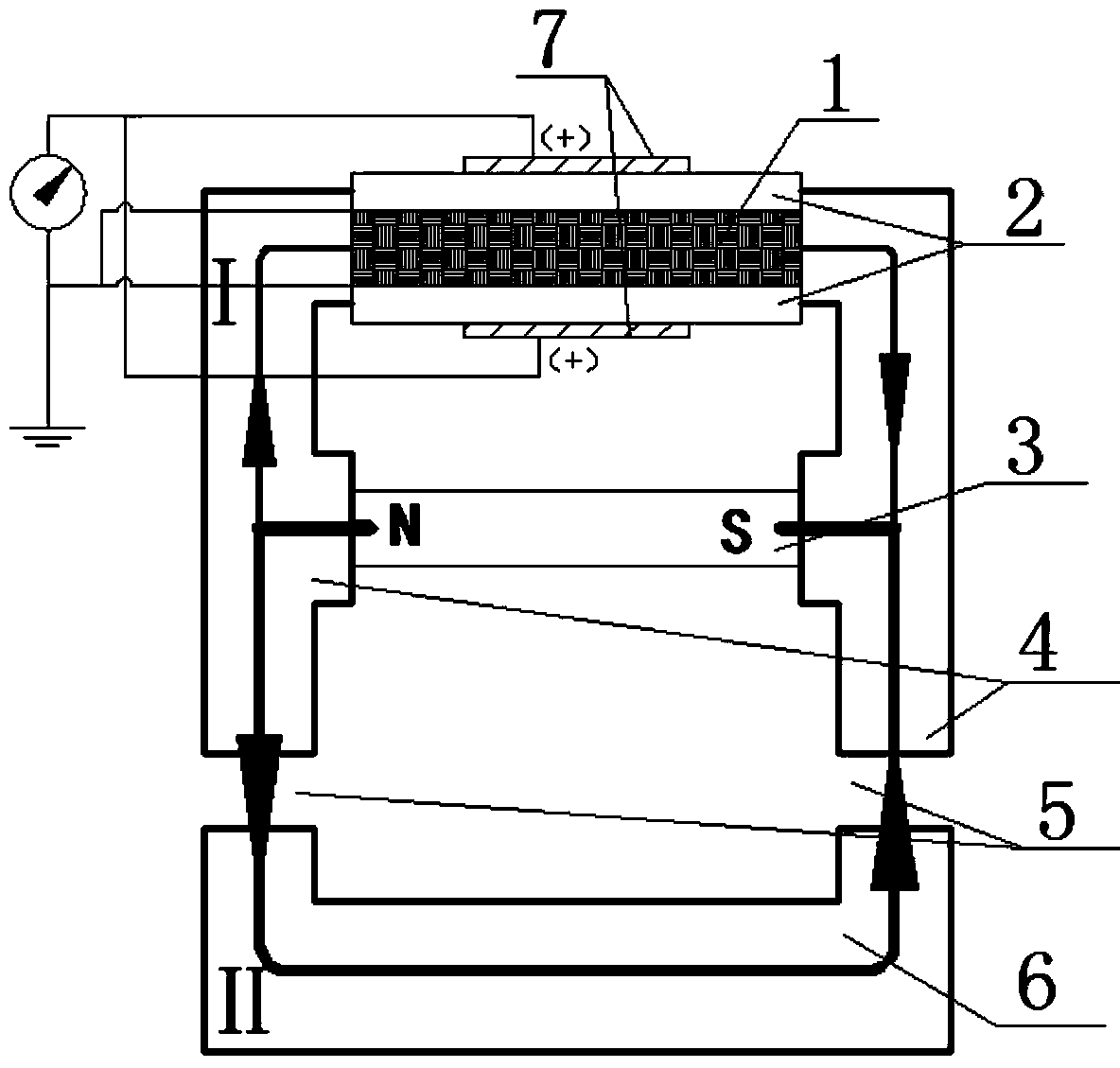
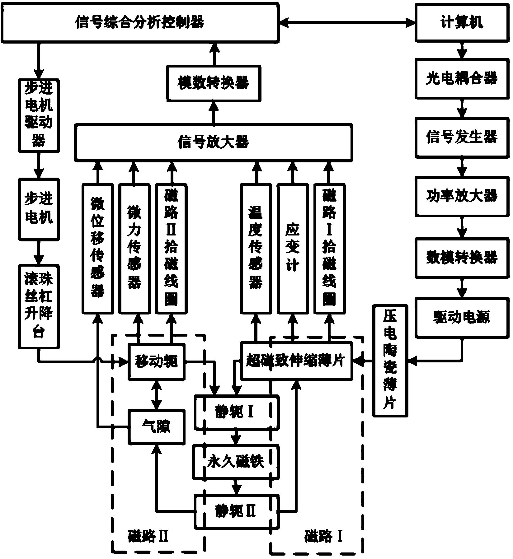
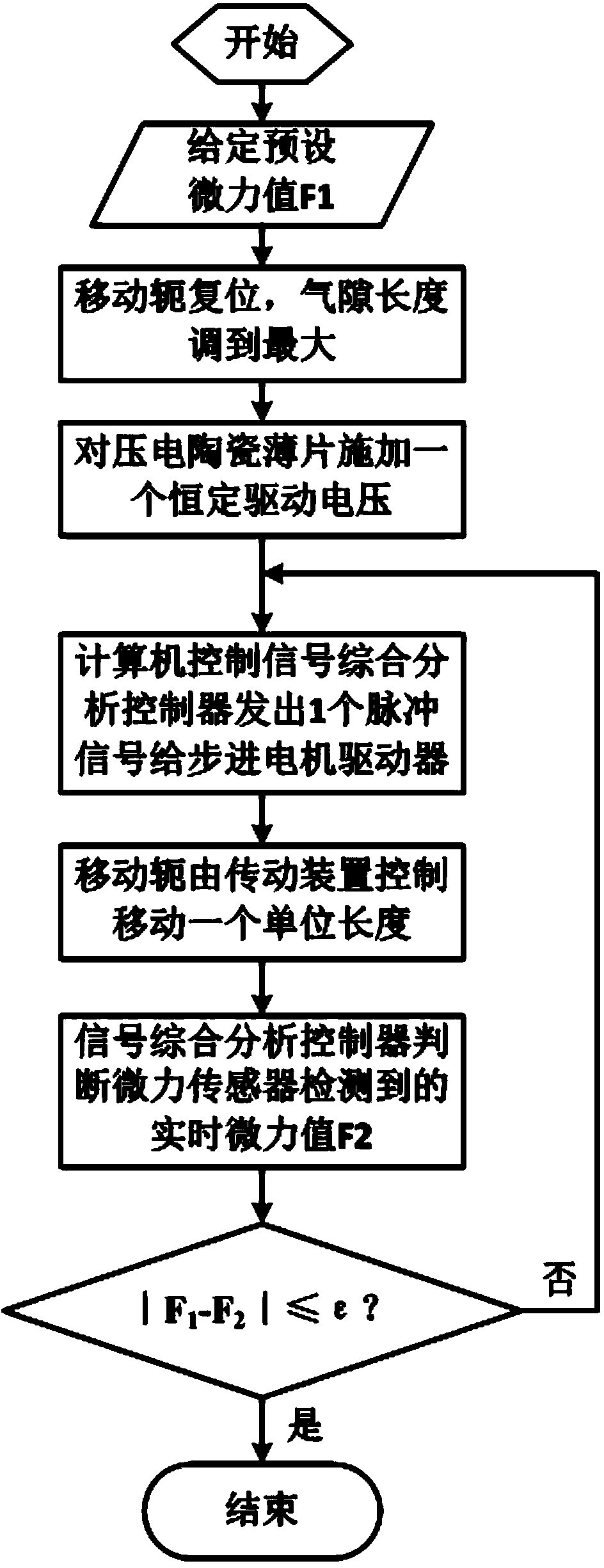
[0021] Embodiment 1, figure 1 A precise regulation method and control system of micro-power are given; the precise regulation control system of micro-power includes micro-power device and micro-power control system.

[0022]The microdynamic device is a magnetic microdynamic device, including a giant magnetostrictive sheet 1 , a static yoke 4 , a permanent magnet 3 and a moving yoke 6 . Static yoke 4 is divided into static yoke I and static yoke II, which are independent of each other. Static yoke I and static yoke II are connected to each other through giant magnetostrictive sheets 1 and permanent magnets 3 which are parallel to each other; One end of the yoke II is provided with a moving yoke 6; the magnetic circuit I is formed between the giant magnetostrictive sheet 1, the static yoke I, the permanent magnet 3 and the static yoke II, and the moving yoke 6, the static yoke II, the permanent magnet 3 and the static yoke Magnetic circuit II formed by I; in the magnetic circui...


PUM


Abstract

The invention discloses a micro-dynamic accurate regulation control system which comprises a micro-dynamic device and a micro-dynamic control system. The micro-dynamic device comprises a magnetic circuit I composed of a giant magnetostrictive sheet, a permanent magnet, a static yoke I and a static yoke II, and a magnetic circuit II composed of a permanent magnet, a static yoke I, a static yoke II and a movable yoke. An air gap is formed in the magnetic circuit II. The magnetic circuit I and the magnetic circuit II are respectively provided with a magnetism regulation device. A piezoelectric ceramic sheet is arranged on the giant magnetostrictive sheet of the magnetic circuit I. The movable yoke of the magnetic circuit II is fixed through a ball screw lifting table driven by a stepping motor. The micro-dynamic control system comprises a sensor set, a signal amplifier, a signal comprehensive analysis controller, a computer, a signal generator, a power amplifier, a digital-to-analog converter and a driving power source, wherein the signal amplifier, the signal comprehensive analysis controller, the computer, the signal generator, the power amplifier, the digital-to-analog converter and the driving power source are sequentially in signal connection. The signal amplifier is connected with the sensor set. The driving power source is electrically connected with the piezoelectric ceramic sheet. The signal comprehensive analysis controller is connected with the stepping motor through a stepping motor driver.

Description

technical field [0001] The invention relates to the field of force adjustment and control, in particular to a precise adjustment method and control system for micro power. Background technique [0002] At present, the development of MEMS is extremely rapid, but there are still some technical bottlenecks. One of the main problems facing MEMS technology is micro-assembly technology. Most micro-electro-mechanical systems are composed of tiny parts of different materials and different processing methods. With the continuous miniaturization of parts, the processing and assembly of micro-systems become more and more difficult. Mechanical damage and thermal deformation damage account for a large proportion of the damage during the transportation, processing and assembly of parts, especially when operating parts that are very sensitive to mechanical contact force or heat, these parts are subject to a small force Or heat will produce deformation or breakage, which has a strong impa...

Claims


Application Information

Patent Timeline
Patent Type & Authority Applications(China)
IPC IPC(8): H02N2/14
Inventor 徐爱群段福斌于海阔葛丁飞杨礼康吴立军
Owner ZHEJIANG UNIVERSITY OF SCIENCE AND TECHNOLOGY
Learn More