Heating components and atomization structures of electronic cigarettes

A technology for electronic cigarettes and heating components, applied in the directions of tobacco, smoker's products, applications, etc., can solve the problems of unsightly fiber rope, easy accumulation of dust, uncleanness, etc. The effect of improving heat utilization

Active Publication Date: 2017-05-31
SHENZHEN KANGER TECH CO LTD
View PDF1 Cites 4 Cited by
  • Summary
  • Abstract
  • Description
  • Claims
  • Application Information

AI Technical Summary

Problems solved by technology

Existing e-cigarette structures use fiber ropes as the liquid guide carrier for the e-liquid from the liquid storage chamber to the hollow atomizing rod and the support carrier for the heating wire to realize the atomization of the e-liquid. However, when the heating wire is at high temperature for a long time If the fiber rope is easy to produce burnt smell, it will seriously affect the taste of electronic cigarettes, and even the fiber rope will be burnt and damaged, which will affect the reliability of the fiber rope. From the appearance, the fiber rope is not beautiful, It is easy to accumulate dust, unclean, etc., and due to the flexible material of the fiber rope, it is usually necessary to set a sealing sleeve 24 outside the upper end of the hollow atomizing rod to fix the fiber rope; in addition, the winding method of the heating wire on the fiber rope It is relatively simple, and cannot better arrange the positional relationship between the liquid on the liquid guide carrier and the heating wire, resulting in waste of raw materials and a reduction in atomization efficiency

Method used


Image

  • Heating components and atomization structures of electronic cigarettes
  • Heating components and atomization structures of electronic cigarettes
  • Heating components and atomization structures of electronic cigarettes

Examples


Embodiment Construction

[0033] In the following, the present invention will be further described in conjunction with the accompanying drawings and specific embodiments, so as to understand the technical idea claimed in the present invention more clearly.

[0034] In the following detailed description of the preferred embodiment, reference is made to the accompanying drawings which form a part hereof. The accompanying drawings show, by way of example, specific embodiments in which the invention can be practiced, and the illustrated embodiments are not intended to exhaust all embodiments according to the invention. It is to be understood that other embodiments may be utilized and structural or logical changes may be made without departing from the scope of the present invention. Accordingly, the following detailed description is not limiting, and the scope of the invention is defined by the appended claims.

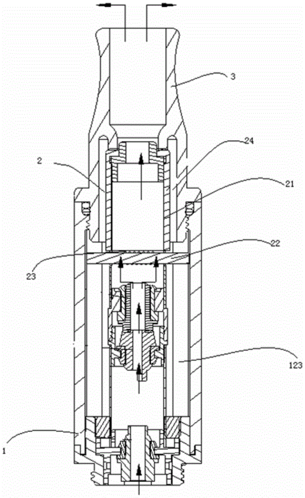
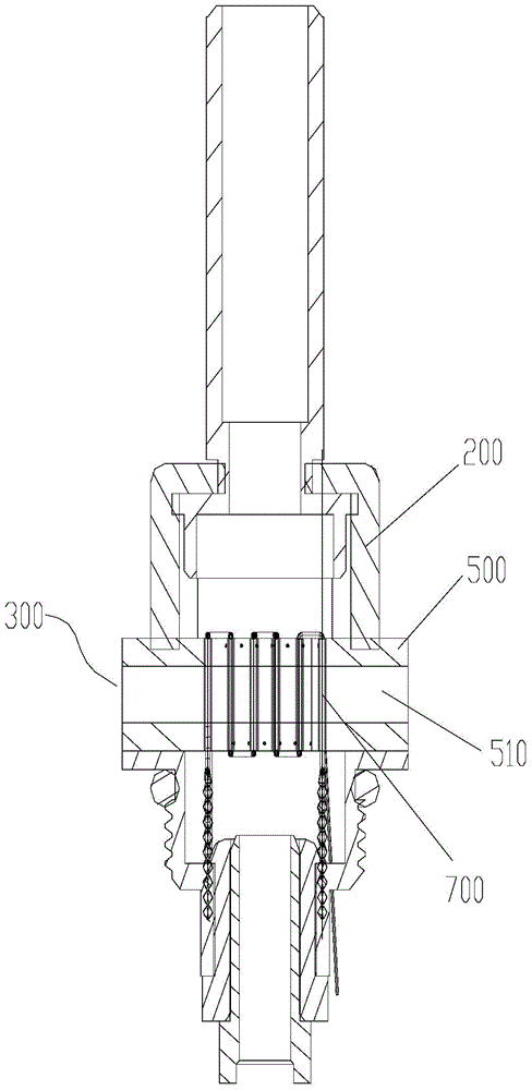
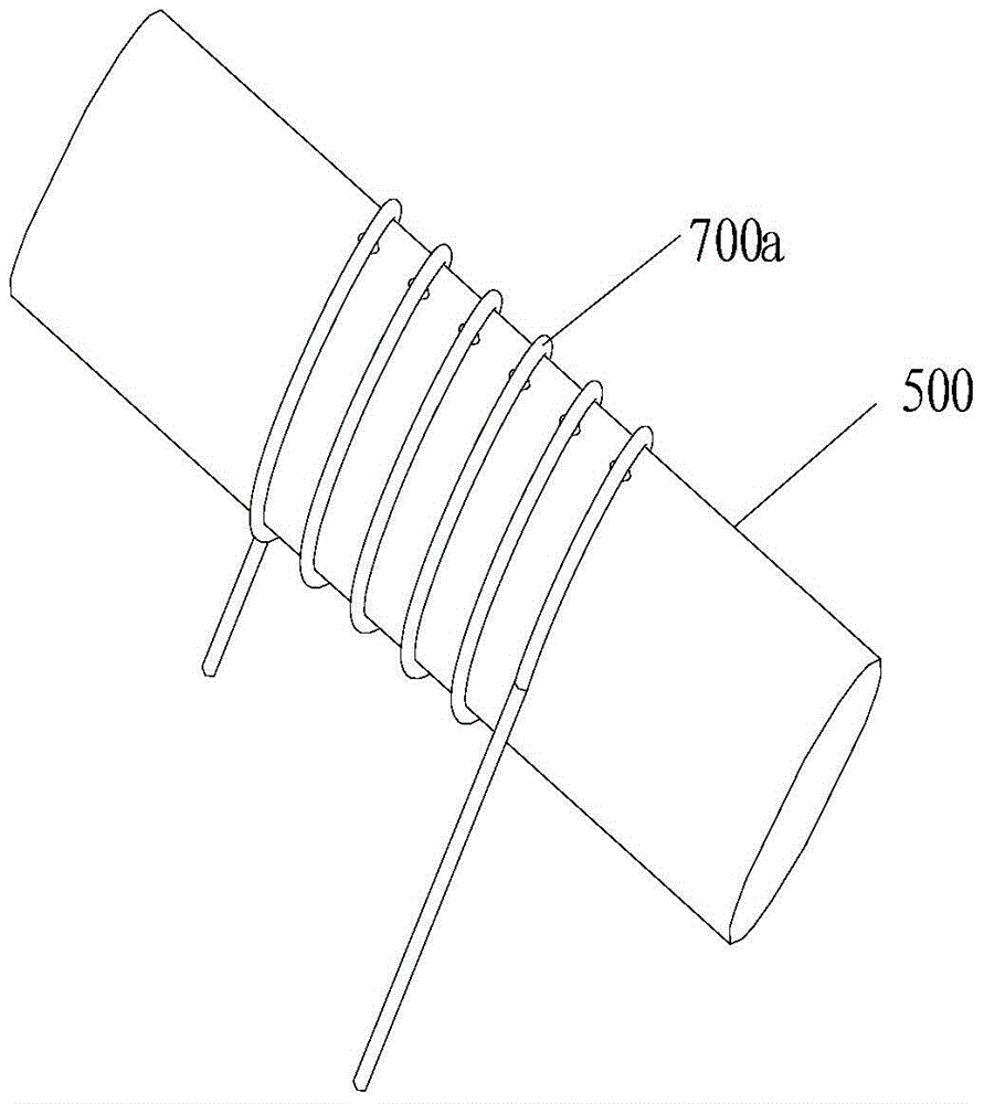
[0035] See figure 2 , the present invention relates to an atomization structure of an elect...


PUM


Abstract

The invention discloses a heating component and an atomizing structure of an electronic cigarette, which comprises a liquid-conducting ceramic rod and a heating wire arranged on the liquid-conducting ceramic rod. In the present invention, the liquid-conducting ceramic rod is used to replace the existing fiber rope as the liquid-conducting carrier from the liquid storage chamber to the hollow atomizing rod and the supporting carrier for the heating wire. It has the characteristics of high temperature resistance and no burning smell, thus The generated airflow is more in line with the requirements of electronic cigarettes, and the taste is closer to real cigarettes; moreover, the liquid-conducting ceramic rod is not easy to damage, and the liquid-conducting is uniform and long-lasting, which can effectively ensure the reliability of liquid-conducting of electronic cigarettes; furthermore, the liquid-conducting ceramic rod The hard material characteristics of the rod can realize various layouts of the heating wire on the liquid-conducting ceramic rod, so that the positional relationship between the liquid on the liquid-conducting carrier and the heating wire can be distributed more reasonably, so as to improve the heat utilization rate and make the mist The chemical effect is obviously improved, and raw materials are saved.

Description

technical field [0001] The invention relates to a heating component of an electronic cigarette. [0002] The invention also relates to an atomization structure of the electronic cigarette. Background technique [0003] With people's recognition of the hazards of traditional cigarettes, electronic cigarettes have gradually become popular. Most of the existing electronic cigarettes are similar to traditional lit cigarettes in appearance and taste. and other harmful substances, so as to achieve the purpose of quitting smoking. [0004] The electronic cigarette is mainly composed of a tobacco rod 1, an atomizer 2 and a cigarette holder 3, and there is a liquid storage chamber 123 for storing smoke liquid defined by the above-mentioned tobacco rod 1, atomizer 2 and cigarette holder 3, see figure 1 . For example, in the Chinese patent application CN201220223286.6, the atomizer 2 mainly includes a hollow atomizing rod 21 with a roughly cylindrical shape, a fiber rope 22 and a he...

Claims


Application Information

Patent Timeline
Patent Type & Authority Patents(China)
IPC IPC(8): A24F47/00A24F40/10A24F40/44A24F40/46
CPCA24F40/46A24F40/10A24F40/44
Inventor 朱晓春
Owner SHENZHEN KANGER TECH CO LTD
Why Eureka
Try Eureka