
Disc slewing support method and slewing support for disc pelletizer

A disc pelletizing machine and slewing bearing technology, which is applied in the direction of granulation in the rotating disk/pot, can solve the problems of non-wearing, short service life, and unstable operation of the slewing bearing, and achieve improved contact strength and service life The effect of improving and improving the rotation accuracy

Active Publication Date: 2016-09-14
湖南光明重型机器制造有限公司
View PDF12 Cites 0 Cited by
  • Summary
  • Abstract
  • Description
  • Claims
  • Application Information

AI Technical Summary

Problems solved by technology

[0010] The technical problem to be solved by the present invention is to propose a disc pelletizer with higher support strength, better stability and wear resistance in view of some deficiencies in the disc rotary support mechanism of the existing disc pelletizer Disc rotary support method and device
The method and device can effectively solve the problems that the disk slewing bearing of the current disk pelletizing machine is not wear-resistant, has short service life and unstable operation

Method used


Image

  • Disc slewing support method and slewing support for disc pelletizer
  • Disc slewing support method and slewing support for disc pelletizer
  • Disc slewing support method and slewing support for disc pelletizer

Examples


Embodiment 1

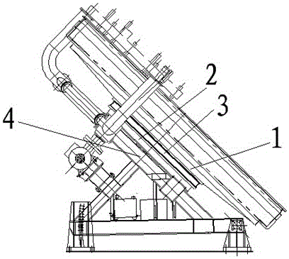
[0031] attached figure 1 An embodiment of the present invention is given, which is a slewing support for a disc pelletizing machine disc, including a disc pelletizing machine disc 1, a disc pelletizing machine base 2 and a disc pelletizing machine disc seat 3. Disc pelletizing machine seat 3 is installed on disc pelletizing machine base 2, disc pelletizing machine disc 1 is located on disc pelletizing machine disc seat 3, and on disc pelletizing machine disc 3 and the disk seat of the disc pelletizing machine is provided with a slewing support 4, and the disk 1 of the disc pelletizing machine can rotate around the center of the disc on the disk seat 3 of the disc pelletizing machine. It is characterized in that the The slewing bearing 4 is a three-row roller slewing bearing, and is installed on the end surface from the outer diameter to the center of the disc pelletizing machine.

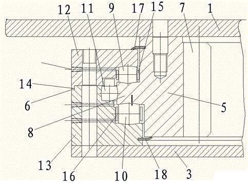
[0032] attached figure 2 A three-row roller slewing bearing 4 is given, including a rotating ...

Embodiment 2

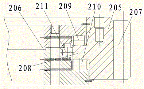
[0037] The structure of embodiment two is as attached image 3 As shown, its basic structure is the same as that of Embodiment 1, except that Embodiment 2 is a disk pelletizing machine with an outer ring gear, the ring gear is an outer ring gear 207, and the boss on the rotating disk 205 is an inner boss , the axes of the rotating disk 205 and the fixed disk 206 are just opposite to those of Embodiment 1, and only two rows of rollers 209 and 211 are spherical rollers among the three rows of rollers, and the other row of rollers 210 is flat rollers.

Embodiment 3

[0039] The structure of embodiment three is as attached Figure 4 As shown, its basic structure is the same as that of Embodiment 2, and it is also a disc pelletizing machine with an outer ring gear, except that the arrangement of the three rows of rollers is different. Two rows of rollers arranged radially, one row of rollers 309 are spherical rollers, the other row of rollers 310 are flat rollers, and the rollers 311 arranged on the circumference are also spherical rollers.


PUM

PropertyMeasurementUnit
diameteraaaaaaaaaa

Abstract

The invention discloses a slewing bearing method for a disc of a disc-type balling machine and a slewing bearing. The disc of the disc-type balling machine is arranged on a disc base of the disc-type balling machine through the slewing bearing and rotates around the center of a main shaft of the disk; the slewing bearing is arranged on an end surface between the disc of the disc-type balling machine and the disc base of the disc-type balling machine and is a three-row roller slewing bearing; the disc of the disc-type balling machine is supported by the slewing bearing consisting of three rows of rollers. By arranging the three-row roller slewing bearing in the middle of the end surface of the disc of the disc-type balling machine, the supporting situation of the disc of the disc-type balling machine is effectively changed; particularly, by the aid of a three-row spherical roller slewing bearing which is spherically centered, the contact strength of rollers and a roller path in an existing three-row spherical roller slewing bearing of the same specifications is improved, and meanwhile, the rotation accuracy is improved as well, so that the rotation stability of the disc of the disc-type balling machine is greatly improved, and the service life of the disc is greatly prolonged.

Description

technical field [0001] The invention relates to a method and device for manufacturing metallurgical equipment, in particular to a method and device for manufacturing green pellets in a pellet production process, and is mainly used for manufacturing disc pelletizers. Background technique [0002] The disc pelletizer is the equipment for making green pellets in the pellet production process. Its structure is composed of a rotating mandrel structure, the disc of the pelletizing machine is supported on the main shaft, the main shaft is hinged to the supporting shaft of the equipment base by two fulcrums at the front end, and the end of the main shaft box is connected to the base through an inclination adjuster. Its working principle is that the inclination angle of the peripheral disc on the body and the horizontal is 30-55 degrees, which can be adjusted arbitrarily within the specified range. The motor drives the disc to rotate through a gear reducer and a pair of bevel gears....

Claims


Application Information

Patent Timeline
Patent Type & Authority Patents(China)
IPC IPC(8): B01J2/14
Inventor 王亦工
Owner 湖南光明重型机器制造有限公司
Learn More