Adjustable turbulence scale inhibitor device and scale inhibition method

A technology of turbulent flow and anti-scaling, which is applied in chemical instruments and methods, descaling and water softening, water/sludge/sewage treatment, etc. The effect cannot be guaranteed and other problems, to achieve the effect of improving the ability to release free electrons, improving the effect of scale inhibition and descaling, increasing the contact area and water flow rate

Pending Publication Date: 2020-05-22
罗光政 +1
View PDF0 Cites 6 Cited by
  • Summary
  • Abstract
  • Description
  • Claims
  • Application Information

AI Technical Summary

Problems solved by technology

However, the existing technical solutions ignore one of the most important prerequisites, that is, the catalyst alloy must meet the conditions of certain water pressure, water flow velocity and contact area to achieve the purpose of scale inhibition.
Therefore, the antiscaling device must be designed according to the water quality, water pressure, water flow velocity and other parameters in different working conditions and usage conditions; more importantly: the water quality in actual industrial production conditions and usage conditions Parameters such as water pressure, water flow velocity, etc. are changing at any time, and the anti-scaling device with a fixed structure cannot meet the changing requirements at all. It must be adjusted in time to achieve the purpose of effective anti-scaling
However, in existing water treatment devices using catalyst alloys, no matter whether the catalyst alloy cylinder core adopts straight holes, spiral holes, blades, spiral blades, rotating blades, or granular or loose sheet structures, the distance between the catalyst alloy sheets in the cylinder core cannot be adjusted. , the descaling process is uncontrollable and belongs to the open state, not only the descaling effect cannot be guaranteed, but even the waterway will be blocked; in addition, this kind of antiscaling device cannot be used under low water pressure conditions

Method used


Image

  • Adjustable turbulence scale inhibitor device and scale inhibition method
  • Adjustable turbulence scale inhibitor device and scale inhibition method
  • Adjustable turbulence scale inhibitor device and scale inhibition method

Examples


Embodiment 1

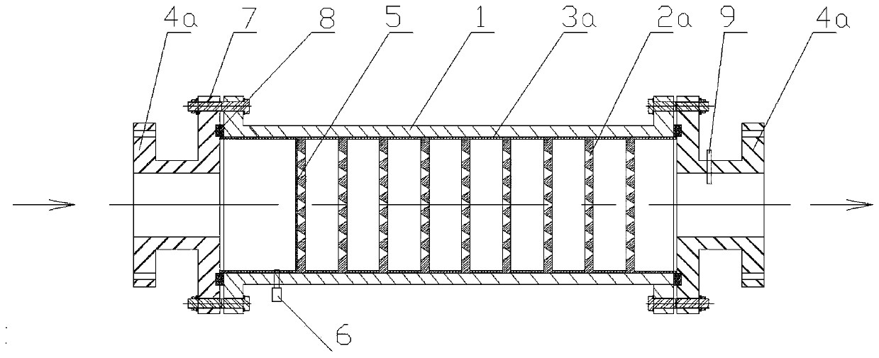
[0067] Such as figure 1 As shown, in this embodiment, an adjustable scale dissolving component in an adjustable turbulent flow scale dissolving device consists of a plurality of disc-shaped turbulent bodies 2a arranged at intervals in the cylinder body 1 and a disc-shaped turbulent body arranged in each disc-shaped turbulent body. 2a, and the isolation sleeve 3a between the disk-shaped turbulent body 2a and the inlet and outlet connectors; both the inlet and outlet connectors are flanges 4a.

[0068] The installation process of the adjustable turbulent flow descaling device is as follows: install the sealing ring 8 in the sealing ring groove of the flange 4a as the outlet connector, and connect the inner flange plate of the flange 4a to the cylinder through the bolt 7 The flanges at one end of the water outlet of 1 are connected together, and then 10 steel spacer sleeves 3a and 9 disc-shaped turbulent bodies 2a are spaced into the cylinder 1; the circular surface of the disc-s...

Embodiment 2

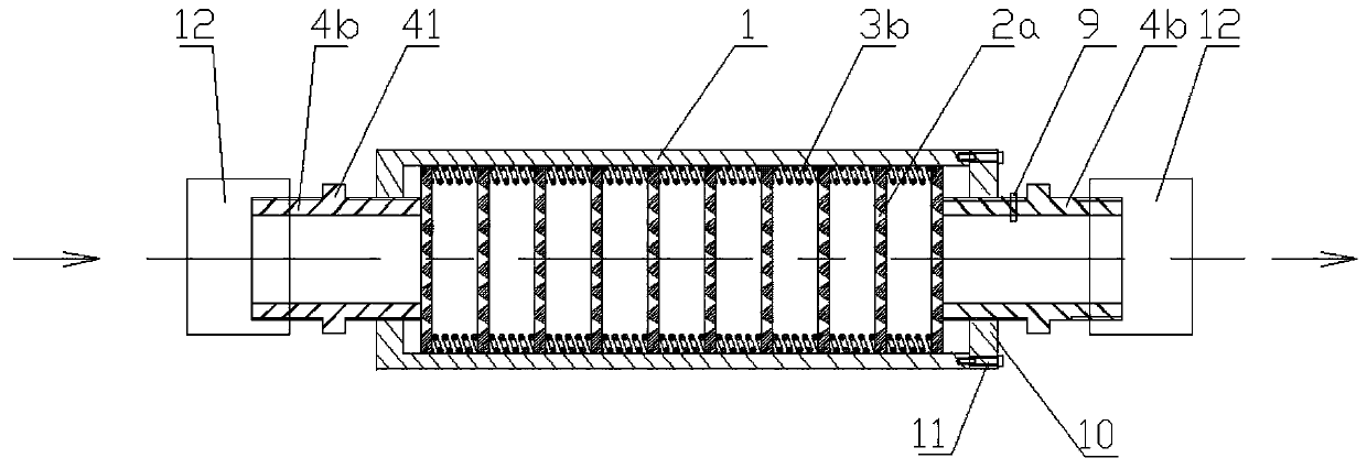
[0071] Such as figure 2 As shown, in this embodiment, an adjustable scale dissolving assembly in an adjustable turbulent flow scale dissolving device consists of a plurality of disc-shaped turbulent bodies 2a arranged at intervals in the cylinder body 1 and a disc-shaped turbulent body arranged in each disc-shaped turbulent body. 2a between a plurality of springs 3b; inlet connectors, outlet connectors are external wire head 4b. The two ends of the cylinder 1 are provided with sealing heads 10, wherein the sealing head 10 at the water inlet end is integrated with the cylindrical body 1, and the sealing head 10 at the water outlet end is an end cap structure, and the end cap structure is integrated with the cylindrical body 1. The corresponding ends are fixedly connected by screws 11.

[0072] The installation process of the adjustable turbulent flow descaling device is as follows: screw the external wire head 4b as the inlet connector into the internal thread hole opened in ...

Embodiment 3

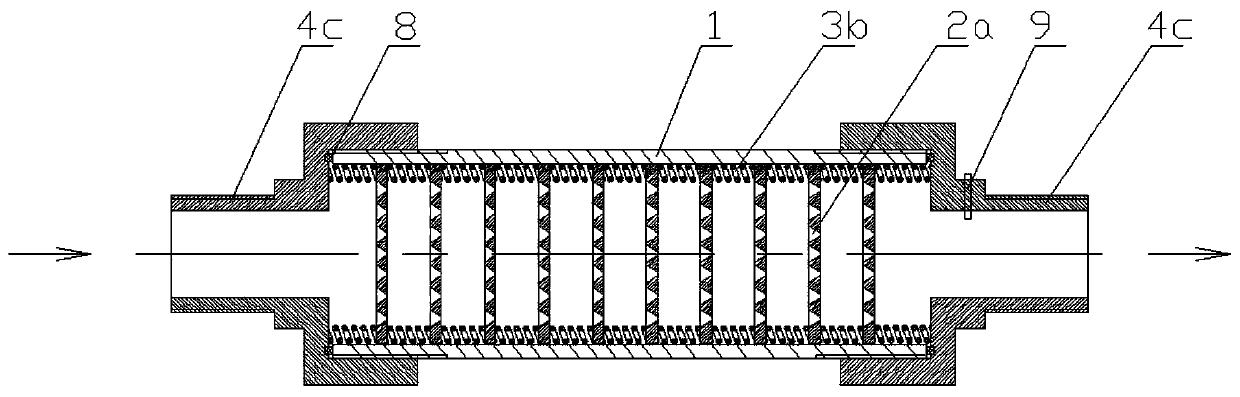
[0075] Such as image 3 As shown, in this embodiment, the adjustable scale dissolving component in the adjustable turbulent flow scale dissolver consists of a plurality of disc-shaped turbulent bodies 2a arranged at intervals in the cylinder body 1 and a plurality of disc-shaped turbulent bodies 2a arranged between each disc-shaped turbulent body 2a , and a plurality of springs 3b between the disc-shaped turbulent body 2a and the inlet connector and the outlet connector; both the inlet connector and the outlet connector are internally threaded bobbins 4c. Both ends of the cylindrical body 1 are provided with external threads.

[0076] When installing the adjustable turbulent flow descaling device, first place the sealing ring 8 in the sealing ring groove on the inner end surface of the two internally threaded bobbins 4c as the inlet connector and the outlet connector, and then place the seal ring 8 as the inlet connector. The inner threaded bobbin head 4c is fixedly connected...


PUM


Abstract

The invention relates to an adjustable turbulence scale inhibitor device and a scale inhibition method. The adjustable turbulence scale inhibitor device comprises a cylinder, an adjustable scale dissolving assembly, an inlet connecting piece and an outlet connecting piece, wherein the adjustable scale dissolving assembly is composed of a plurality of turbulence bodies, and the distance among the turbulence bodies can be adjusted; the turbulence bodies are made of a catalyst alloy; one end of the cylinder is a water inlet, and the other end of the cylinder is a water outlet; the inlet connecting piece is arranged at one end of the water inlet of the cylinder, and the outlet connecting piece is arranged at one end of the water outlet of the cylinder. According to the device and the method, the turbulent flow body interval or the system water pressure in the scale dissolving assembly can be adjusted according to the dynamically detected water flow speed value, so that the purpose of stable scale inhibition is achieved.

Description

technical field [0001] The invention relates to the technical field of water treatment equipment, in particular to an adjustable turbulent flow scale inhibitor and a scale inhibitor method. Background technique [0002] In petroleum, chemical industry, steel, heating, thermal power and other industrial and civil production fields, water is needed as a medium to transfer energy. However, since the water contains non-water-soluble sediments formed by calcium and magnesium ions, silt, clay and other substances, when the dissolution conditions change or long-term use of these substances, they will deposit on the surface of the pipeline or container to form scale, resulting in pipeline failure. The diameter becomes smaller or even the pipeline is blocked. This phenomenon not only affects production efficiency and energy transfer efficiency, but may also cause accidents such as pipeline bursts, resulting in a series of economic losses and great harm. [0003] In order to prevent...

Claims


Application Information

Patent Timeline
Patent Type & Authority Applications(China)
IPC IPC(8): C02F5/00
CPCC02F5/00
Inventor 罗光政王华平罗显龙孙晓帆刘哲罗显贺黄华赵玲赵妍
Owner 罗光政
Why Eureka
Try Eureka