High-efficiency dephosphorization method and high-efficiency dephosphorization device

A high-efficiency and protective device technology, applied in the direction of metal processing equipment, metal rolling, manufacturing tools, etc., can solve the problem of low flow efficiency and achieve the effects of reduced spray speed, broad market and economic benefits, and improved service life

Inactive Publication Date: 2014-06-18
FUJIAN DEXING ENERGY CONSERVATION TECH
View PDF12 Cites 9 Cited by
  • Summary
  • Abstract
  • Description
  • Claims
  • Application Information

AI Technical Summary

Problems solved by technology

Because under the same strike pressure condition, the flow rate is proportional to the jet distance, the flow efficiency of the traditional high-pressure water dephosphorization method is relatively low, generally less than 10% (flow efficiency = water beam thickness in the core pressure area required for dephosphorization ÷ dephosphorization surface Actual water beam thickness × 100%)

Method used


Image

  • High-efficiency dephosphorization method and high-efficiency dephosphorization device
  • High-efficiency dephosphorization method and high-efficiency dephosphorization device
  • High-efficiency dephosphorization method and high-efficiency dephosphorization device

Examples


Embodiment 1

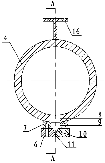
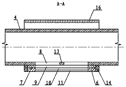
[0037] Embodiment one: if Figure 2~4 As shown, an integrated high-efficiency dephosphorization device includes an integral pressure-bearing chamber 4 for circulating a dephosphorization medium and an injection section 5 for spraying a dephosphorization medium, and the pressure-receiving chamber 4 is provided with a dephosphorization medium Inlet, the lower side wall of the pressure chamber 4 is provided with an outlet channel 8 for the dephosphorization medium, and the outlet part 12 of the injection section is a long and narrow slit, so that the flow jet sprayed on the surface of the metal blank is non-destructive. Diffused flake shape, the injection section 5 is fixed at the outlet channel 8 of the pressure chamber through the joint section 7, the two ends of the injection section 5 are provided with sealing plates 14, and the pressure chamber is provided with Rib 16.

[0038] In this embodiment, the pressure-receiving chamber 4 is a pipe with a circular axial cross-sectio...

Embodiment 2

[0042] Embodiment two: if Figure 5 As shown, a split-type high-efficiency phosphorus removal device, the split-type pressure-bearing chamber 15 is spliced ​​by two semicircular grooves on the left and right, and the spray block can be integrated with the semicircular groove, or can be independent After it is made, it is connected to the semi-circular groove.

Embodiment 3

[0043] Embodiment three: as Image 6 As shown, a split-type high-efficiency dephosphorization device with a partition, a partition 17 is arranged in the middle of the two semicircular grooves, and the partition forms two disconnected partitions inside the pressure chamber. The compartments are all provided with independent phosphorus removal medium inlets and spray outlet channels.

[0044] When using gas, liquid (or solid) as the phosphorus removal medium, when the gas medium is sprayed out, a negative pressure will be generated near the outlet section, and the liquid (or solid) phosphorus removal medium will be sucked out to complete the descaling together. By setting the guide mechanism (For example: using the Coanda Effect——Coanda Effect) and other measures can reduce the distance between the outlet sections of the two injection sections and improve the utilization rate of negative pressure (the specific implementation method is not shown in the drawings).


PUM


Abstract

The invention relates to a high-efficiency dephosphorization method and a high-efficiency dephosphorization device. The high-efficiency dephosphorization device comprises a pressure-bearing cavity for circulating a phosphorization medium, wherein the pressure-bearing cavity is provided with a phosphorization medium inlet, the side wall, adjacent to the surface of a to-be-dephosphorized metal blank, of the pressure-bearing cavity is provided with an injection outlet passage of the dephosphorization medium, the injection outlet passage is a slender slot, so that the stream injected to the surface of the metal blank is in a non-dispersion sheet shape. The pressure-bearing cavity is a pipeline with an circular axial cross section, the pipeline is integrally formed or formed by splicing two semicircular grooves, and the pressure-bearing cavity is in a bar shape, an annular shape or a special shape. The dephosphorization medium is in a non-dispersion sheet form after being injected, the pressure is basically not scattered, so that the utilization efficiency of the pressure is improved, the injection speed of the dephosphorization stream is reduced, the service life of the dephosphorization device is prolonged; moreover, the high-efficiency dephosphorization device is not subjected to the limitation of the installation condition, the injection distance of the dephosphorization stream can be reduced, and the flow efficiency can be improved.

Description

technical field [0001] The invention relates to the field of high-pressure water dephosphorization of metal blanks in the metallurgical industry, in particular to a method and device for highly efficient dephosphorization. Background technique [0002] The metal billet (steel billet or copper billet, etc.) is in a high temperature state during the rolling process, and the surface will be oxidized due to contact with air, forming a dense oxide skin (ie phosphor skin). The process of removing this layer of scale before rolling is descaling, which can improve rolling quality and roll service life. [0003] Such as figure 1 As shown, the traditional phosphorus removal method is to use fan-shaped phosphorus removal nozzle 2, under the action of high-pressure water, to form a fan-shaped water jet 3 with impact force (with a certain angle with metal billet 1), which is used to cut and wash metal billet 1 Oxide skin on. [0004] The phosphorus removal device used in the tradition...

Claims


Application Information

Patent Timeline
Patent Type & Authority Applications(China)
IPC IPC(8): B21B45/08
CPCB21B45/08
Inventor 梅保胜
Owner FUJIAN DEXING ENERGY CONSERVATION TECH
Why Eureka
Try Eureka