A kind of device and method for fiber drawing coating

A coating device and coating technology, applied in the field of optical fiber manufacturing, can solve problems such as increased operating procedures, decreased optical power, scratched optical fibers, etc., to achieve the effects of improving production stability, increasing curing uniformity, and reducing the number of operations

Active Publication Date: 2016-08-17
TONGDING INTERCONNECTION INFORMATION CO LTD +1
View PDF1 Cites 0 Cited by
  • Summary
  • Abstract
  • Description
  • Claims
  • Application Information

AI Technical Summary

Problems solved by technology

If the distribution of the number of curing devices is unbalanced, it will directly affect the uniformity of the curing degree of the inner and outer coating materials.
In addition, due to the attenuation of power during the use of the curing device, the central glass tube is polluted by volatiles of the coating material, etc., the actual optical power of individual or part of the curing device will drop sharply, thus affecting the curing uniformity of the inner and outer coatings.
[0007] (2) The operation process is complicated
Since the first layer of inner coating cup is separated from the second layer of outer coating coating cup, the operation process increases, the mold cleaning process needs to clean two molds, and the wire drawing operation process requires two mold penetrations and two penetrations into the curing system Operation, the whole process is easy to introduce impurities and scratch the optical fiber
[0008] (3) Increased probability of fiber failure
Since the first layer of inner coating cup is separated from the second layer of outer coating coating cup, the outlet of the first layer coating mold will adhere to the volatiles generated during the curing process of the optical fiber, and the uncleanness of the mold outlet increases the contact between the bare optical fiber and foreign matter chance to directly affect the strength of the fiber
In addition, after the first layer is cured, the second layer is coated, which is easy to produce ripples at the interface between the first layer and the second layer, which increases the coating defect rate of the optical fiber.

Method used


Image

  • A kind of device and method for fiber drawing coating
  • A kind of device and method for fiber drawing coating
  • A kind of device and method for fiber drawing coating

Examples


Embodiment Construction

[0025] In order to make the technical means, creative features, goals and effects achieved by the present invention easy to understand, the present invention will be further described below in conjunction with specific embodiments.

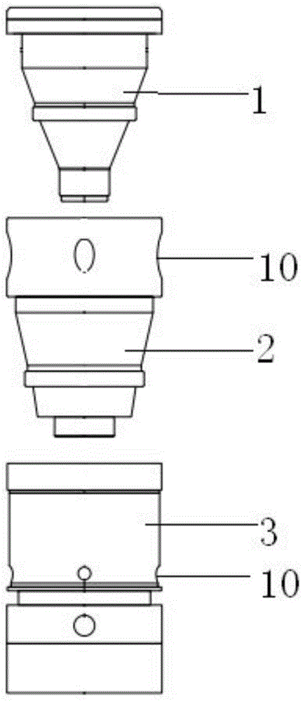
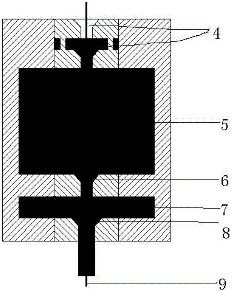
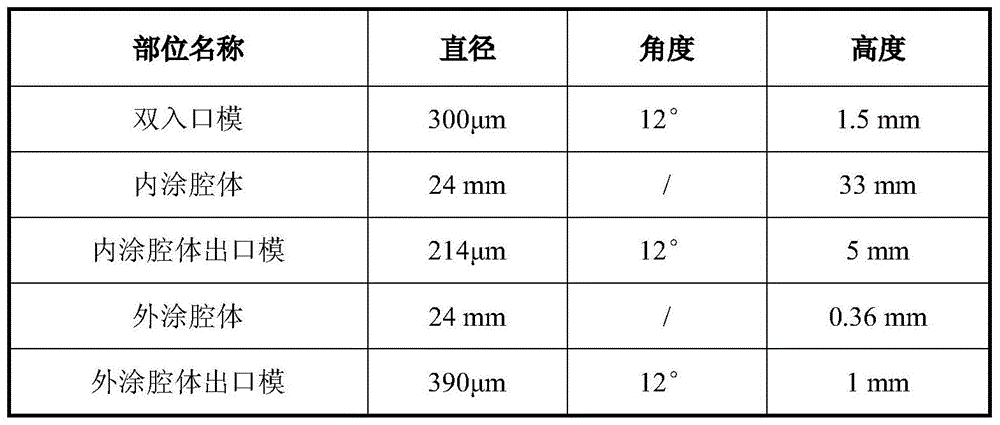
[0026] refer to figure 1 , figure 2 and image 3 , the present invention comprises three through threaded connection assembly, and thread is the inlet die 1 of triangular thread, sizing die 2 and coating die 3, and described inlet die 1, sizing die 2 and coating die 3 have concentric optical fiber Perforation, the inlet mold 1 is a double inlet mold 4, the inlet mold 1 has a height of 1.5 mm, an inner diameter of 300 μm, and a slope angle of 12°. The first inlet mold and the second inlet mold are provided with a distance. The coating mold 3. Set the inner coating cavity 5 and the outer coating cavity 7, the inner coating cavity 5 is connected with the second inlet mold, the height of the inner coating cavity is 33mm, the inner diameter is 24mm,...


PUM

PropertyMeasurementUnit
heightaaaaaaaaaa
heightaaaaaaaaaa
angleaaaaaaaaaa

Abstract

The invention relates to the field of optical fiber manufacturing, in particular to a device and method for drawing and coating optical fibers. The device for drawing and coating optical fiber comprises an inlet mold, a sizing mold and a coating mold which are connected in sequence, the inlet mold, the sizing mold and the coating mold have concentric optical fiber holes, the inlet mold is a double inlet mold, the first inlet mold is spaced from the second inlet mold, the coating mold is provided with an inner coating cavity connected with the second inlet mold and an outer coating cavity connected with the inner coating cavity, each of the mold outlets of the inlet mold, the sizing mold and the coating mold is provided with a slope. The probability of introduction of impurities and volatilization of inner-coating volatile matters to an outer-coating cup can be reduced during inner curing, the curing uniformity of the fiber is increased, the ripples generated on an outer-coating interface after curing of inner-coating volatile matters in optical fiber are avoided and UV light curing space needed after the application of the inner coating is eliminated. The cooling space is increased for drawing optical fibers at a high speed.

Description

technical field [0001] The invention relates to the field of optical fiber manufacturing, in particular to a device and method for drawing and coating an optical fiber. Background technique [0002] Today, the drawing technology for optical fiber production has been developing rapidly, mainly in two aspects: the size of the optical fiber preform is getting larger and the drawing speed is getting faster and faster. In particular, high-speed wire drawing technology has become one of the most direct and effective ways to reduce the cost of optical fiber. [0003] To increase the fiber drawing speed, the fiber needs more cooling space. When the height of the factory building and the drawing tower is fixed, the traditional wet-to-dry coating process occupies a large height space for the system itself, resulting in limited cooling space for the optical fiber, so there is little room for increasing the drawing speed of the optical fiber. For the traditional wet-to-dry coating pro...

Claims


Application Information

Patent Timeline
Patent Type & Authority Patents(China)
IPC IPC(8): C03C25/16
Inventor 沈小平田锦成向德成沈国锋孙谦何炳
Owner TONGDING INTERCONNECTION INFORMATION CO LTD
Why Eureka
Try Eureka