Sleeve type dip pipe for RH (Ruhrstahl Hereaeus) vacuum refining device

A technology of vacuum refining and dipping tube, applied in the field of refining outside the molten steel furnace, can solve the problems of increasing the structural size of the dipping tube, and achieve the effects of prolonging the period of maintenance and final scrapping, reducing the maximum speed and reducing the amount of cold steel attached

Active Publication Date: 2014-06-18
NORTHEASTERN UNIV
View PDF3 Cites 13 Cited by
  • Summary
  • Abstract
  • Description
  • Claims
  • Application Information

AI Technical Summary

Problems solved by technology

[0020] (3) The dipping tube needs to be inserted into the ladle when it is working, and increasing the structural size of the dipping tube is severely restricted by the size of the ladle

Method used


Image

  • Sleeve type dip pipe for RH (Ruhrstahl Hereaeus) vacuum refining device
  • Sleeve type dip pipe for RH (Ruhrstahl Hereaeus) vacuum refining device
  • Sleeve type dip pipe for RH (Ruhrstahl Hereaeus) vacuum refining device

Examples


Embodiment Construction

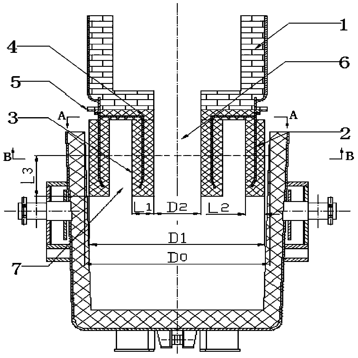
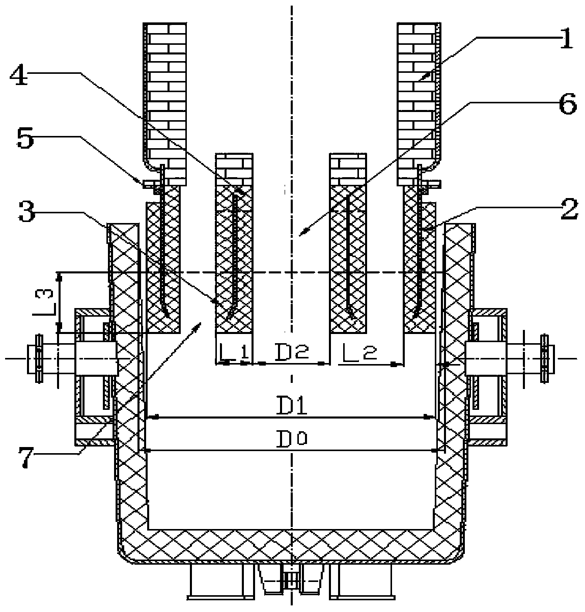
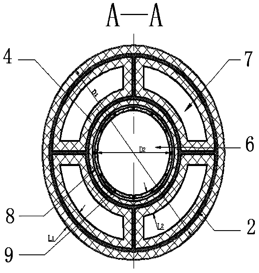
[0041] The present invention will be further described by taking the inner circular tube as the rising tube and the outer circular tube as the downcomer as an example. Such as figure 1 , figure 2 , image 3 and Figure 4As shown, the sleeve-type dipping tube used in the RH vacuum refining device of the present invention is mainly composed of an annular sleeve 2, a circular tube-shaped partition wall 3, a beam 4 and a flange 5, wherein: the annular sleeve 2 is the dipping tube The outer tube of the circular tube-shaped partition wall 3 is set up in the middle of the annular casing 2 and is coaxial with the annular casing 2. The girder 4 has an inner hole, and the diameter of the girder inner hole is consistent with the inner diameter of the tubular partition wall 3, and the steel structure inside the refractory lining is welded and fixed with the steel structure at the top of the tubular partition wall. The outer end of the girder is provided with 4 fin plates at an angle ...


PUM

PropertyMeasurementUnit
thicknessaaaaaaaaaa

Abstract

The invention discloses a sleeve type dip pipe for an RH (Ruhrstahl Hereaeus) vacuum refining device. The dip pipe mainly comprises an annular sleeve pipe, a circular-pipe-shaped partition wall, a cross beam and a flange plate, wherein the circular-pipe-shaped partition wall is coaxially arranged in the middle of the annular sleeve pipe; an inner circular pipe is formed on the inner side of the circular-pipe-shaped partition wall; an outer annular pipe is formed between the outer wall of the circular-pipe-shaped partition wall and the inner wall of the annular sleeve pipe on the outer side of the circular-pipe-shaped partition wall; the inner annular pipe and the outer annular pipe can be used as an ascending pipe and a descending pipe of the RH dip pipe respectively. As the space in the bottom of a vacuum chamber is fully utilized by the dip pipe with the structure to enlarge the circulation area of molten steel of the dip pipe, the circulation flow of an RH vacuum circulation degassing device can be remarkably increased.

Description

technical field [0001] The invention relates to the field of external refining of molten steel, in particular to a dip tube used in an RH vacuum refining device. Background technique [0002] In the field of refining outside the furnace, the vacuum refining equipment for molten steel mainly includes RH, VD and other devices. RH refers to an integral or split vacuum chamber. When processing molten steel, all metallurgical reactions are carried out in the vacuum chamber. The bottom of the RH is two circular dipping tubes, which are the ascending pipe and the descending pipe respectively. The upper part is connected The hot bending pipe is connected with the vacuum system, and each part is combined into a set of vacuum refining device. [0003] The entire metallurgical reaction process of RH is carried out in a vacuum chamber lined with refractory bricks. When the dipping tube is inserted into the molten steel, the vacuum chamber is started to be evacuated. At this time, unde...

Claims


Application Information

Patent Timeline
Patent Type & Authority Applications(China)
IPC IPC(8): C21C7/10
Inventor 许涛邹宗树
Owner NORTHEASTERN UNIV
Why Eureka
Try Eureka