
Combined type snow removing and ice melting vehicle

A compound and snow-melting technology, which is applied in snow surface cleaning, cleaning methods, construction, etc., can solve the problems of high investment cost of vehicle-mounted boilers, reduction of road surface adhesion coefficient, economic loss, etc., and achieve high snow removal efficiency, good snow removal effect, The effect of strong mobility

Inactive Publication Date: 2014-06-18
SHANDONG UNIV OF TECH
View PDF5 Cites 6 Cited by
  • Summary
  • Abstract
  • Description
  • Claims
  • Application Information

AI Technical Summary

Problems solved by technology

Ice and snow greatly reduce the adhesion coefficient of the road surface, causing the car to skid, significantly prolong the braking distance, and even lose control of the direction, resulting in serious traffic accidents
The problem of ice and snow on the road surface has always plagued the transportation departments of various countries. The snow and ice on the road lead to the closure of the highway and the suspension of the aircraft, causing huge economic losses.
Although these methods are effective, they also bring a series of problems. For example, the problem caused by mechanical snow throwing is that a large amount of snow needs to be stored or transported in time; the vehicle-mounted boiler has high investment costs, high energy consumption and low efficiency; Ice and snow shoveling is suitable for clearing large areas of snow before freezing. When removing snow on the road, although the ice and snow are cleaned, many roads have been damaged to varying degrees; mechanical snow blowing is suitable for unrolled thicker areas. Thin road snow is usually only suitable for small-scale snow removal that is easy to manage, such as airports, and it is difficult to promote it on a large scale

Method used


Image

  • Combined type snow removing and ice melting vehicle
  • Combined type snow removing and ice melting vehicle
  • Combined type snow removing and ice melting vehicle

Examples


Embodiment Construction

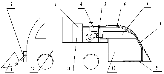
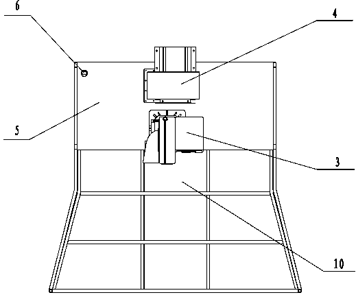
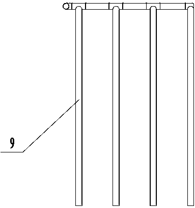
[0013] 1. Mechanical shovel; 2. Mechanical shovel lifting mechanism; 3. Direct-fired burner; 4. Vortex fan; 5. Rack; 6. High pressure air pipe; 7. Fire cover; 8. Heat exchanger; 9. High pressure air flow Nozzle; 10, combustion chamber; 11, air compressor; 12, car body.

[0014] The present invention will be further described below in conjunction with specific drawings.

[0015] The compound snow removal and ice melting vehicle of the present invention comprises: a mechanical shovel 1, a mechanical shovel lifting mechanism 2, a direct-fired burner 3, a vortex fan 4, a frame 5, a high-pressure air pipe 6, a fire cover 7, a heat exchanger 8, High pressure air flow nozzle 9, combustion chamber 10, air compressor 11, car body 12.

[0016] For road sections with serious snow and ice, the mechanical shovel lifting mechanism 2 lowers the mechanical shovel 1, and the mechanical shovel 1 performs preliminary snow removal and ice breaking on the ice and snow on the road surface; 10 fla...


PUM


Abstract

A combined type snow removing and ice melting vehicle is composed of a mechanical snow removing device, a vehicle body and a snow melting device. The mechanical snow removing device is arranged at the front end of the vehicle body and comprises a mechanical shovel and a mechanical shove lifting mechanism, and the height of the mechanical shovel can be adjusted according to the circumstance of snow accumulated on the surface of a road; the snow melting device is arranged at the rear end of the vehicle body through a machine frame and comprises a direct-fired burner, an eddy current fan, the machine frame, a high-pressure air pipe, a fire cover, a heat exchanger, a high-pressure air current spray pipe, a combustion chamber and an air compressor. High-speed air currents formed by the eddy current fan by leading air in are blown towards the ground through the fire cover and the combustion chamber; high-pressure air currents formed by the air compressor by leading air in are blown towards the ground sequentially through the high-pressure air pipe, the heat exchanger and the high-pressure air current spray pipe, the heat exchanger is a steel pipe coiled inside the combustion chamber, and after heat exchange is conducted on the high-pressure air through the coiled steel pipe, the high-pressure air is blown towards the ground through the high-pressure air current spray pipe so as to melt the snow.

Description

technical field [0001] The invention relates to a compound snow removal and ice melting vehicle, which belongs to the field of special vehicles. Background technique [0002] In the cold winter, the snow and ice on the road will have a serious adverse effect on the smoothness of the road and driving safety. Ice and snow greatly reduce the adhesion coefficient of the road surface, causing the car to skid, significantly prolonging the braking distance, and even losing control of the direction, resulting in serious traffic accidents. The problem of ice and snow on the road surface has always plagued the transportation departments of various countries. The snow and ice on the road lead to the closure of expressways and the suspension of aircraft, causing huge economic losses. Therefore, in order to ensure smooth roads and driving safety, avoid or reduce traffic accidents, improve road capacity and operational efficiency, measures must be taken to remove ice and snow from the ro...

Claims


Application Information

Patent Timeline
IPC IPC(8): E01H5/10
Inventor 石沛林张橹李朋超罗丽
Owner SHANDONG UNIV OF TECH
Learn More