
Injection type hollow resin anchor bar

An internal injection and bolt technology, which is used in the installation of bolts, mining equipment, earth-moving drilling, etc., can solve the problems of large pushing resistance, difficult to push the bolt to the bottom of the hole to install in place, and unreasonable force on the bolt. , to achieve the effect of reasonable stress on the anchor rod, simplify the anchoring construction operation, and reduce the maintenance workload.

Inactive Publication Date: 2014-06-18
高原
View PDF7 Cites 10 Cited by
  • Summary
  • Abstract
  • Description
  • Claims
  • Application Information

AI Technical Summary

Problems solved by technology

[0003] 1. In order to ensure that the anchor rod can be installed in place within a short period of time before the anchoring agent solidifies, the diameter of the drill hole is increased to reduce the installation resistance of the anchor rod. Basically, the diameter of the drill hole is 10 to 12 mm larger than the diameter of the anchor rod , resulting in a large volume of space between the anchor rod and the hole wall that needs to be densely packed with anchoring agent, and the filling volume of the anchoring agent is limited, so the anchor rod can only be installed in the way of end anchoring, and the anchor rod is stressed during work. Unreasonable, and when there are too many medicine rolls, the pushing resistance after stirring is too large, and it is difficult to complete the installation
[0004] 2. During the construction of complex or broken rock formations, the ability to form or maintain the form of the hole is very poor. After the drilling tool is withdrawn, it is difficult to push the anchor rod to the bottom of the hole and install it in place, resulting in installation failure. It must be manually removed and replaced. bit re-drilled for installation

Method used


Image

  • Injection type hollow resin anchor bar

Examples


Embodiment Construction

[0013] In order to make the technical means, creative features, goals and effects achieved by the present invention easy to understand, the technical solutions in the embodiments of the present invention will be clearly and completely described below in conjunction with the accompanying drawings in the embodiments of the present invention.

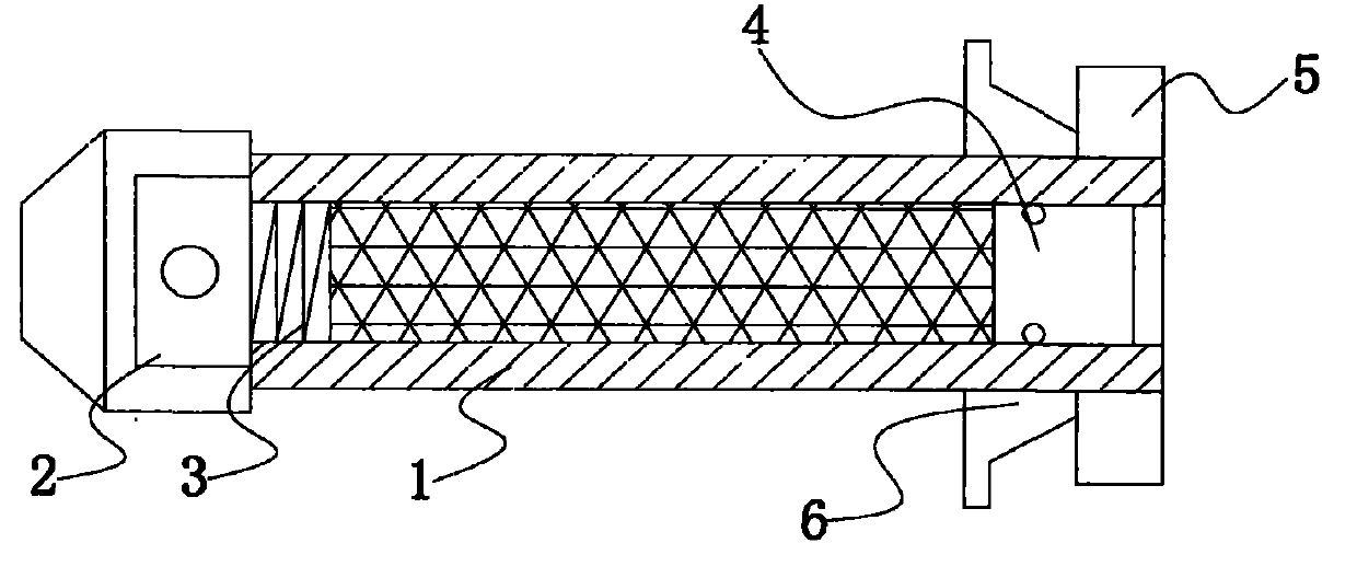
[0014] see figure 1 , the specific embodiment is realized by adopting the following technical scheme, which includes an anchor body 1, an anchor head 2, a mixer 3, a piston 4 and a nut 5; the outer wall of the anchor body 1 is provided with a long external thread , the inside of which is provided with a hollow medicament cavity, the front end of the anchor body 1 is provided with an anchor head 2, and the rear end is screwed and matched with the external thread on the surface of the anchor body 1 through a nut 5, the medicament cavity One end is provided with a piston 4 that fits the inner wall of the medicine chamber, and the other end is...


PUM


Abstract

The invention discloses an injection type hollow resin anchor bar which comprises an anchor bar body, an anchor head, a mixer, a piston and a nut. An elongated external thread is arranged on the outer wall of the anchor bar body, a hollow agent cavity is formed inside the anchor bar body, the anchor head 2 is arranged at the front end of the anchor bar body, the rear end of the anchor bar body is matched with the external thread on the surface of the anchor bar body in a screwed manner through the nut, the piston fitting the inner wall of the agent cavity is arranged at one end of the agent cavity, the mixer is arranged at the other end of the agent cavity, one end of the mixer is connected with the anchor head, and a cutting edge is arranged at the other end of the mixer. By the aid of a full-length anchoring mode, the anchor bar is more reasonable in stress, maintenance workload of the mounted anchor bar can be largely decreased, resin anchoring agents enter an anchor hole and are solidified after appropriate anchoring agents prefilled in an anchor bar cavity are pressurized, and anchoring construction operation can be simplified.

Description

technical field [0001] The invention relates to the field of anchoring appliances, in particular to an inner-injection hollow resin anchor rod. Background technique [0002] At present, the construction and installation process of bolt support in underground shafts of coal mines is as follows: use a bolter to drill a hole, clean the hole after the drilling depth reaches the requirement, withdraw the drilling tool, insert the anchoring resin medicine roll into the hole, and then use the bolt Withstand the drug roll and start the anchor drilling rig to slowly rotate the anchor and quickly push the anchor to the bottom of the hole. After the anchor is in place, stop rotating and wait for the resin anchoring agent to solidify (the anchoring resin usually takes one and a half minutes from stirring to solidification) Left and right), remove the rock bolt rig, install the butterfly backing plate and nut, and tighten the nut to the predetermined requirement to complete the bolt inst...

Claims


Application Information

Patent Timeline
IPC IPC(8): E21D21/00
Inventor 高原
Owner 高原
Learn More