Method and system for determining value of variable on radio frequency (RF) transmission model

A technology of transmission lines and variables, applied in the field of variable values, can solve problems such as not knowing whether the system is running normally

Inactive Publication Date: 2014-06-18
LAM RES CORP
View PDF2 Cites 3 Cited by
  • Summary
  • Abstract
  • Description
  • Claims
  • Application Information

AI Technical Summary

Problems solved by technology

This avoidance of probes can lead to uncertainty as to whether a plasma-based system is functioning properly

Method used


Image

  • Method and system for determining value of variable on radio frequency (RF) transmission model
  • Method and system for determining value of variable on radio frequency (RF) transmission model
  • Method and system for determining value of variable on radio frequency (RF) transmission model

Examples


Embodiment Construction

[0038] The following embodiments describe systems and methods for determining the value of a variable on a radio frequency (RF) transmission line. It may be evident that the embodiments may be practiced without some or all of these specific details. In other instances, well known process operations have not been described in detail so as not to unnecessarily obscure the embodiments.

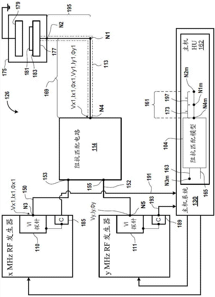
[0039] figure 1 is a block diagram of an embodiment of the system 126 for determining variables at the output of the impedance matching model 104 and at the output (e.g., model node N1m) of the portion 173 of the RF transmission model 161, which is the RF transmission line 113 models. The RF transmission line 113 has an output, eg, node N2. Voltage and current (VI) probe 110 measures complex voltage and current Vx, Ix and For example, the first complex voltage and current. It should be noted that Vx represents the magnitude of the voltage, Ix represents the magnitude of the current, and R...


PUM


Abstract

Systems and methods for determining a value of a variable on a radio frequency (RF) transmission model are described. One of the methods includes identifying a complex voltage and current measured at an output of an RF generator and generating an impedance matching model based on electrical components defined in an impedance matching circuit coupled to the RF generator. The method further includes propagating the complex voltage and current through the one or more elements from the input of the impedance matching model and through one or more elements of an RF transmission model portion that is coupled to the impedance matching model to determine a complex voltage and current at the output of the RF transmission model portion.

Description

technical field [0001] The present invention relates to determining the value of a variable on a radio frequency (RF) transmission line. Background technique [0002] In plasma-based systems, a plasma is generated when process gases are supplied into a plasma chamber and radio frequency (RF) is supplied to electrodes within the plasma chamber. Plasma-based systems are used to perform various operations on wafers. For example, plasmas are used to etch wafers, deposit materials on wafers, clean wafers, and the like. [0003] During the performance of these operations, points within the plasma-based system may be monitored to determine whether the plasma-based system is functioning properly. The points are monitored using probes. However, using probes in plasma-based systems can be expensive. For example, some entities may avoid the use of probes to avoid the cost of the probes. This avoidance of probes can lead to uncertainty as to whether a plasma-based system is functio...

Claims


Application Information

Patent Timeline
Patent Type & Authority Applications(China)
IPC IPC(8): H01J37/147H01P3/08
CPCG01R19/2516H05H1/46H03H7/40H01J37/32183H01J37/32935H01P3/00H01J37/32926G06F30/367H05H2242/26G01R19/25G01R29/0892H01J2237/327
Inventor 约翰·C·小瓦尔考布拉德福德·J·林达克
Owner LAM RES CORP
Why Eureka
Try Eureka