Intermittent linear conveying device
A transmission device, linear technology, applied in the direction of transportation and packaging, conveyor objects, electrical components, etc., can solve the inconsistency of the movement of the moving claw and the positioning claw, reduce the transmission speed and work efficiency, and the equipment is difficult to run stably and other problems, to achieve the effect of saving detection time, stable rotation, and accurate horizontal movement
- Summary
- Abstract
- Description
- Claims
- Application Information
AI Technical Summary
Problems solved by technology
Method used
Image
Examples
Embodiment 1
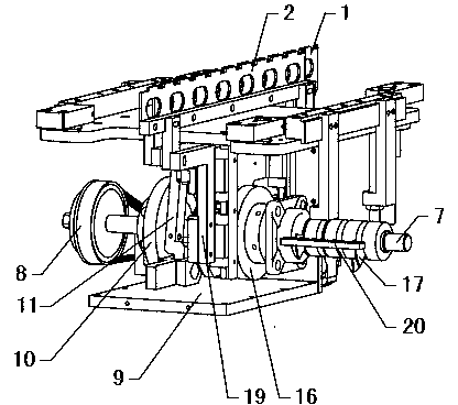
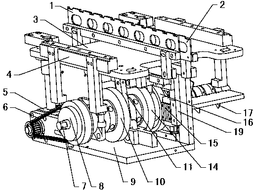
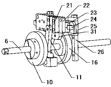
[0037] refer to Figure 1~2 , an intermittent linear transmission device, including a servo motor 5, a transmission shaft 7, a material shifting cam 10, a positioning cam 14 and a material shifting lifting cam 16, the servo motor 5 drives the timing belt pulley 8 to rotate through the timing belt 6, and the timing pulley 8 is coaxial It is fixed on the end of the transmission shaft 7 to drive the transmission shaft 7 to rotate. The material shifting cam 10, the positioning cam 14 and the material shifting lifting cam 16 are all fixed on the transmission shaft 7, which can ensure the synchronization of the rotation of each cam and improve the transmission accuracy. Simultaneously, the structure is simple and compact. The material shifting cam 10 drives the material shifting claw 1 to move horizontally back and forth through the material shifting connecting rod 11, and the material shifting lifting cam 16 drives the material shifting claw 1 to rise and fall. The positioning ca...
Embodiment 2
[0044] refer to Figure 6 The difference between this embodiment and Embodiment 1 is that it also includes a material transfer tension spring 27 and a fine-tuning mechanism, a vertical front side plate 36 is fixed on the front side of the transmission shaft 7, and a vertical rear side plate 36 is fixed on the rear side Plate 37, one end of the material transfer tension spring 27 is a fixed end, which is fixedly connected with the upper fixed plate 3, and the other end is a movable end, which is fixedly connected with the horizontal sliding plate 22, and the material transfer roller 40 and the material transfer roller 40 are compensated by the material transfer spring 27. The gap between the guide grooves of the cam 10 makes the material transfer roller 40 roll along the outer side of the guide groove all the time to ensure that the transmission position is accurate. The fine-tuning mechanism includes a fixed block 34 and a fine-tuning rod 12. The lower end of the material-movi...
Embodiment 3
[0046] refer to Figure 7 , The difference between this embodiment and Embodiment 2 is that a material-moving pressure spring 28 is fixed between the front side plate 36 and the horizontal sliding plate 22, because the material-moving tension spring 27 has a high frequency of repeated actions and a very short life. The compression spring 28 reduces the force that the material-moving tension spring 27 bears, which can effectively prolong the service life of the material-moving tension spring 27. The free end of the material-moving compression spring 28 is fixedly connected with the horizontal sliding plate 22 through the compression spring fixed block 39. The material-moving compression spring 28 is coaxially sleeved with a guide shaft, and the fixed end of the material-moving compression spring 28 is fixedly connected with the guide shaft. The guide shaft passes through The compression spring adjusting bolt 29 is fixed on the front side plate 36, and the guide shaft is adjuste...
PUM
 Abstract
Description
Claims
Application Information
 - R&D
- Intellectual Property
- Life Sciences
- Materials
- Tech Scout
- Unparalleled Data Quality
- Higher Quality Content
- 60% Fewer Hallucinations
Browse by: Latest US Patents, China's latest patents, Technical Efficacy Thesaurus, Application Domain, Technology Topic, Popular Technical Reports.
© 2025 PatSnap. All rights reserved.Legal|Privacy policy|Modern Slavery Act Transparency Statement|Sitemap|About US| Contact US: help@patsnap.com


