Intermittent linear conveying device

A transmission device and linear technology, applied in the direction of transportation and packaging, conveyor objects, electrical components, etc., can solve the inconsistency between the movement of the moving claw and the positioning claw, reduce the transmission speed and work efficiency, and make the equipment difficult to run stably and other problems to achieve the effects of saving detection time, long service life and stable cam rotation

Active Publication Date: 2014-06-18
SHANDONG CAIJU ELECTRONICS TECH CO LTD
View PDF4 Cites 15 Cited by
  • Summary
  • Abstract
  • Description
  • Claims
  • Application Information

AI Technical Summary

Problems solved by technology

In order to ensure accurate transmission and prevent inconsistency between the movement of the moving claw and the positioning claw, and damage to the object to be conveyed, the other cylinder can move further after detecting that one cylinder is in place, and each detection takes more than 200 milliseconds, which is a waste of time. A lot of time directly affects the transmission efficiency, reduces the transmission speed and work efficiency, and the accuracy of the cylinder transmission is poor. When the cylinder moves, the vibration is large, and the whole machine is difficult to maintain stable operation. The life of the cylinder is short, and it usually needs to be replaced every 1-2 years.

Method used


Image

  • Intermittent linear conveying device
  • Intermittent linear conveying device
  • Intermittent linear conveying device

Examples


Embodiment 1

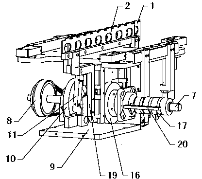
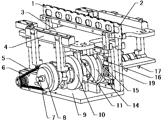
[0037] refer to Figure 1~2 , an intermittent linear transmission device, including a servo motor 5, a transmission shaft 7, a material shifting cam 10, a positioning cam 14 and a material shifting lifting cam 16, the servo motor 5 drives the timing belt pulley 8 to rotate through the timing belt 6, and the timing pulley 8 is coaxial It is fixed on the end of the transmission shaft 7 to drive the transmission shaft 7 to rotate. The material shifting cam 10, the positioning cam 14 and the material shifting lifting cam 16 are all fixed on the transmission shaft 7, which can ensure the synchronization of the rotation of each cam and improve the transmission accuracy. Simultaneously, the structure is simple and compact. The material shifting cam 10 drives the material shifting claw 1 to move horizontally back and forth through the material shifting connecting rod 11, the material shifting lifting cam 16 drives the material shifting claw 1 to rise and fall, the positioning cam 14 d...

Embodiment 2

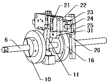
[0044] refer to Image 6 The difference between this embodiment and Embodiment 1 is that it also includes a material transfer tension spring 27 and a fine-tuning mechanism, a vertical front side plate 36 is fixed on the front side of the transmission shaft 7, and a vertical rear side plate 36 is fixed on the rear side Plate 37, one end of the material transfer tension spring 27 is a fixed end, which is fixedly connected with the upper fixed plate 3, and the other end is a movable end, which is fixedly connected with the horizontal sliding plate 22, and the material transfer roller 40 and the material transfer roller 40 are compensated by the material transfer spring 27. The gap between the guide grooves of the cam 10 makes the material transfer roller 40 roll along the outer side of the guide groove all the time to ensure that the transmission position is accurate. The fine-tuning mechanism includes a fixed block 34 and a fine-tuning rod 12. The lower end of the material-movin...

Embodiment 3

[0046] refer to Figure 7 , The difference between this embodiment and Embodiment 2 is that a material-moving pressure spring 28 is fixed between the front side plate 36 and the horizontal sliding plate 22, because the material-moving tension spring 27 has a high frequency of repeated actions and a very short life. The compression spring 28 reduces the force that the material-moving tension spring 27 bears, which can effectively prolong the service life of the material-moving tension spring 27. The free end of the material-moving compression spring 28 is fixedly connected with the horizontal sliding plate 22 through the compression spring fixed block 39. The material-moving compression spring 28 is coaxially sleeved with a guide shaft, and the fixed end of the material-moving compression spring 28 is fixedly connected with the guide shaft. The guide shaft passes through The compression spring adjusting bolt 29 is fixed on the front side plate 36, and the guide shaft is adjuste...


PUM


Abstract

The invention discloses an intermittent linear conveying device, and belongs to the field of conveying equipment for intermittently and linearly conveying objects. A material moving cam (10) is connected with a material moving connecting rod (11), the material moving connecting rod (11) is connected to a vertical guide mechanism in a sliding mode, and a material moving shifting pawl (1) is fixedly connected with the vertical guide mechanism. The vertical guide mechanism is horizontally arranged on a vertical sliding plate (31) in a sliding mode, the vertical sliding plate (31) is vertically arranged in a sliding mode and is connected with a material moving lifting cam (16), the material moving cam (10) drives the material moving shifting pawl (1) to advance or retreat in place through the material moving connecting rod (11), and the material moving lifting cam (16) drives the material moving shifting pawl (1) to ascend and descend through the vertical sliding plate (31). A locating cam (14) is connected with a locating connecting rod (35) which is vertically arranged in a sliding mode, a locating shifting pawl (2) is fixedly connected with the locating connecting rod (35), and the locating cam (14) drives the locating shifting pawl (2) to ascend and descend. The intermittent linear conveying device has the advantages of being accurate in conveying position and reliable in motion, improving work efficiency and the like.

Description

technical field [0001] The invention belongs to the field of transmission equipment for intermittent linear transmission of objects. Background technique [0002] The traditional structure to realize the intermittent linear and accurate movement of the object to be transported generally uses a cylinder as the power. The precise movement of the object to be transported requires the use of shifting claws and positioning claws. The positioning claws move up and down to position the object to be transported and move the material The claw moves forward→fall→reverse→rise→forward in a circular reciprocating motion, thereby linearly moving the object to be transported. When the material transfer claw is in the forward and rising state, the positioning claw is in the downward state. When the material shifting claw is in the falling and backward state At this time, the positioning claw is in the rising state. At least 3 cylinders and many auxiliary devices are required to complete th...

Claims


Application Information

Patent Timeline
Patent Type & Authority Applications(China)
IPC IPC(8): H01L21/677
CPCH01L21/67766
Inventor 李向东王振源路通
Owner SHANDONG CAIJU ELECTRONICS TECH CO LTD
Why Eureka
Try Eureka