

Secondary battery
A secondary battery and current collector foil technology, applied in secondary batteries, secondary battery manufacturing, battery electrodes, etc., can solve the problems of shortened driving distance, reduced capacity of lithium-ion secondary batteries, and inability to exert full output, etc., to achieve Effect of high output performance and maintaining capacity
- Summary
- Abstract
- Description
- Claims
- Application Information
AI Technical Summary
Problems solved by technology
Method used
Image

Examples
no. 1 example )
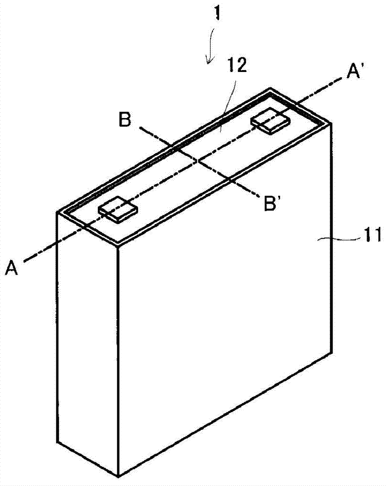
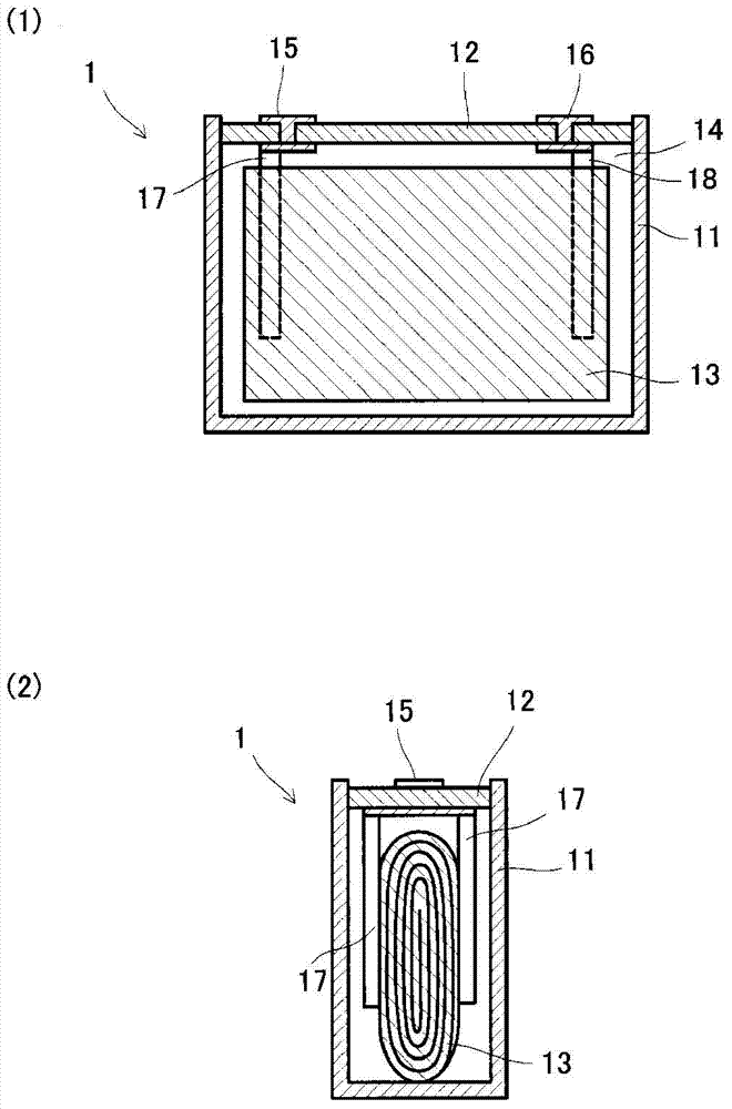
[0041] use figure 1 and figure 2 A first embodiment of the present invention will be described. figure 1 is a perspective view showing a secondary battery (lithium ion secondary battery) according to the present embodiment, figure 2 (1) is shown along the figure 1 The sectional view of the A-A' line, figure 2 (2) is shown along the figure 1 The cross-sectional view of the B-B' line.
[0042] The secondary battery 1 of the present invention is mounted in, for example, an electric vehicle. The secondary battery 1 includes a substantially rectangular parallelepiped case 11 and a cover 12 arranged at an opening of the case 11 to seal the case 11 . like figure 2 As shown, the housing 11 accommodates the electrode body 13 . In addition, an electrolytic solution 14 is injected into the casing 11 , and the electrode body 13 is immersed in the electrolytic solution 14 . The electrode body 13 is formed by laminating and winding a positive electrode plate and a negative elec...
no. 2 example )
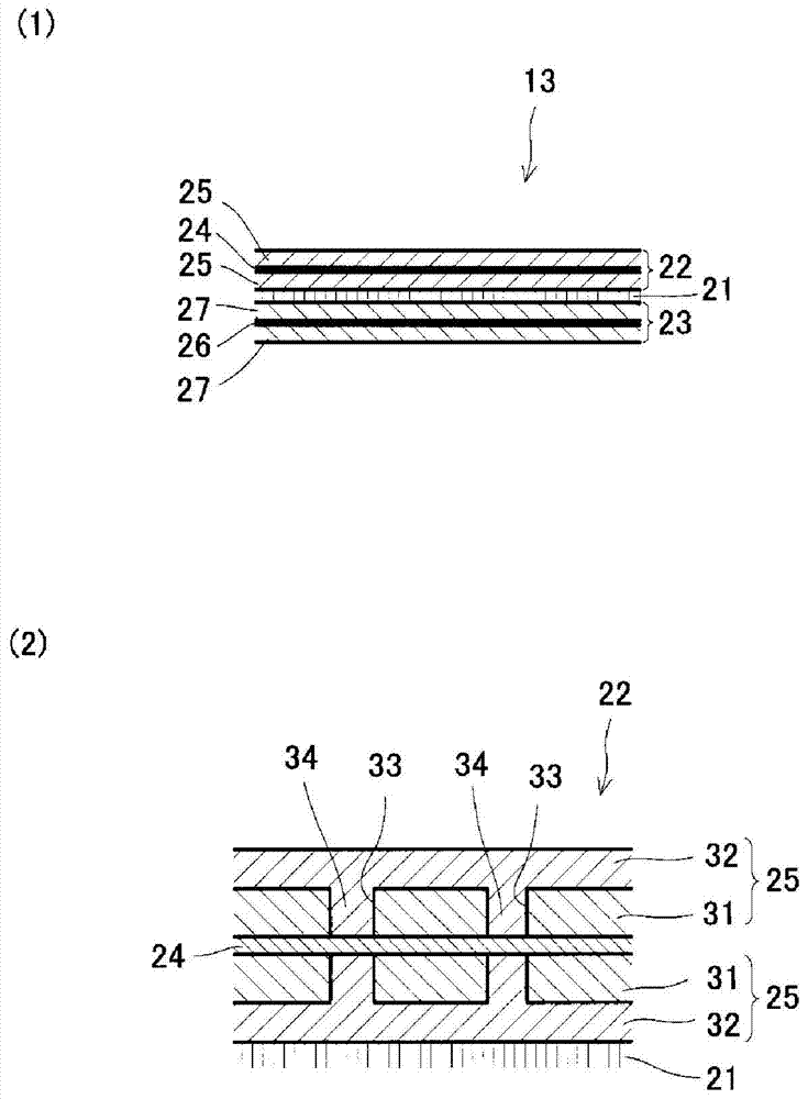
[0069] In the first embodiment described above, the positive electrode collector foil 24 and the second positive electrode layer 32 are electrically connected through the second positive electrode portion 34, but in this embodiment, as Figure 5 As shown, the difference is that the positive electrode collector foil 24A and the second positive electrode layer 32A are electrically connected by a conductive member 35A. In addition, in this embodiment, for convenience of description, the current collector foil and the positive electrode active material layer on the side of the separator are omitted.
[0070]In this embodiment, a through hole 33A is formed in the first positive electrode layer 31A, and the inside of the through hole 33A is buried with a conductive member 35A. Therefore, in the present embodiment, the second positive electrode layer 32A and the positive electrode collector foil 24A are connected by the conductive member 35A. The conductive member 35A is not particu...
PUM
| Property | Measurement | Unit |
|---|---|---|
| The average particle size | aaaaa | aaaaa |
| Thickness | aaaaa | aaaaa |
| Average particle diameter | aaaaa | aaaaa |
Abstract
Description
Claims
Application Information