AI technical title is built by Patsnap AI team. It summarizes the technical point description of the patent document.
A linear power supply and resistance technology, applied in electrical components, regulating electrical variables, instruments, etc., can solve problems such as inability to accurately control the output current
Active Publication Date: 2014-06-18
RIGOL
View PDF11 Cites 1 Cited by
Summary
Abstract
Description
Claims
Application Information
AI Technical Summary
This helps you quickly interpret patents by identifying the three key elements:
Problems solved by technology
Method used
Benefits of technology
Problems solved by technology
[0005] The main purpose of the embodiments of the present invention is to provide a linear power supply to solve the defect that the existing linear power supply cannot precisely control the output current due to the existence of wire resistance and terminal contact resistance
Method used
Image
Click on the blue label to locate the original text in one second.
Reading with bidirectional positioning of images and text.
Examples
Embodiment 1
[0060] This embodiment provides a linear power supply, such as Figure 4 As shown, the linear power supply includes: rectification filter circuit S, transistor Q1, diode D1, error amplifier, sampling resistor Rs, differential amplifier, first resistor R1, second resistor R2, third resistor R3, fourth resistor R4, Five resistors R5 and sixth resistor R6;
[0061] The positive output terminal of the rectification filter circuit S is connected to the collector of the triode tube, and the negative output terminal is connected to the negative output terminal of the linear power supply;
[0062] The base of the triode Q1 is connected to the anode of the diode D1;
[0063] One end of the sampling resistor Rs is connected to the emitter of the triode Q1, and the other end is connected to the positive output end of the linear power supply;
[0064] The cathode of the diode D1 is connected to the output terminal of the error amplifier;
[0065] The non-inverting input terminal of the...
Embodiment 2
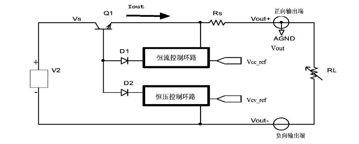
[0102] This embodiment provides another linear power supply, such as Image 6 As shown, the linear power supply includes: rectification filter circuit S, transistor Q1, diode D1, error amplifier, sampling resistor Rs, non-inverting amplifier, first resistor R1, second resistor R2, fifth resistor R5 and sixth resistor R6;
[0103] The positive output terminal of the rectification filter circuit S is connected to the collector of the triode tube, and the negative output terminal is connected to the negative output terminal of the linear power supply;
[0104] The base of the triode Q1 is connected to the anode of the diode D1;
[0105] One end of the sampling resistor Rs is connected to the emitter of the triode Q1, and the other end is connected to the positive output end of the power supply;
[0106] The cathode of the diode D1 is connected to the output terminal of the error amplifier;
[0107] The non-inverting input terminal of the error amplifier is grounded;
[0108] One...
PUM
Abstract
The invention provides a linear power supply characterized by comprising a commercial power port, a transformer, a rectifier bridge, a capacitor, a triode, a diode, an error amplifier, a sampling resistor, a difference amplifier, a first resistor, a second resistor, a third resistor, a fourth resistor, a fifth resistor and a sixth resistor; the invention also provides another linear power supply comprising a commercial power port, a transformer, a rectifier bridge, a capacitor, a triode, a diode, an error amplifier, a sampling resistor, a noninverting amplifier, a first resistor, a second resistor, a fifth resistor and a six resistor. Two ends of the sampling resistor are regarded as sampling points so as to obtain voltage, the obtained voltage is inputted to the difference amplifier or the noninverting amplifier; because one end of the sampling resistor and an inner reference point of the linear power supply are not the sampling points, so error resistance formed by a wire resistor and a terminal contact resistor can be shielded, thereby accurately controlling the current passing the sampling resistor, so the output current of the linear power supply can be more accurate.
Description
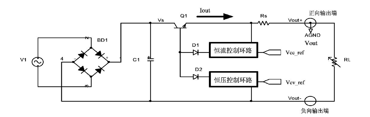
technical field [0001] The present invention relates to the technical field of power supplies, in particular to a linear power supply. Background technique [0002] At present, laboratory power supplies are mostly based on linear principles, such as figure 1 The circuit structure diagram of a typical linear power supply is shown, where V1 is the mains port (including transformer), BD1 is the rectifier bridge, C1 is the capacitor, Q1 is the linear adjustment tube, Rs is the sampling resistor, Vcc_ref is the constant current reference voltage, Vcv_ref is the constant voltage reference voltage, RL is the load, Vout+ is the voltage of the positive output terminal, Vout- is the voltage of the negative output terminal, the circuit uses the positive output terminal as the internal reference ground AGEND, constant current control loop and constant voltage control The loop is connected to the base of the linear adjustment transistor Q1 through an AND gate circuit composed of diodes ...
Claims
Application Information
Patent Timeline
Application Date:The date an application was filed.
Publication Date:The date a patent or application was officially published.
First Publication Date:The earliest publication date of a patent with the same application number.
Issue Date:Publication date of the patent grant document.
PCT Entry Date:The Entry date of PCT National Phase.
Estimated Expiry Date:The statutory expiry date of a patent right according to the Patent Law, and it is the longest term of protection that the patent right can achieve without the termination of the patent right due to other reasons(Term extension factor has been taken into account ).
Invalid Date:Actual expiry date is based on effective date or publication date of legal transaction data of invalid patent.

