IGBT (Insulated Gate Bipolar Translator) inverted pedal type welding machine control circuit

A control circuit, pedal technology, applied in manufacturing tools, welding equipment, welding accessories, etc., can solve the problems of low welding accuracy, complex control circuit, influence, etc., and achieve good welding effect and accurate output current effect.

Pending Publication Date: 2021-10-01
NINGBO EUROPA WELDING & CUTTING TECH
View PDF10 Cites 0 Cited by
  • Summary
  • Abstract
  • Description
  • Claims
  • Application Information

AI Technical Summary

Problems solved by technology

However, the quality of the welding machine will be affected by many factors, such as circuit board design, control circuit, manufacturing process, etc. These factors will eventually affect the market competitiveness of the product
[0004] At present, the control circuit design of the welding machine in the market will adopt the IGBT inverter method, but the control circuit of the IGBT inverter is more complicated, which makes the manufacturing process complicated and the current output of the welding machine is not accurate enough, and sometimes it cannot meet the welding requirements. current
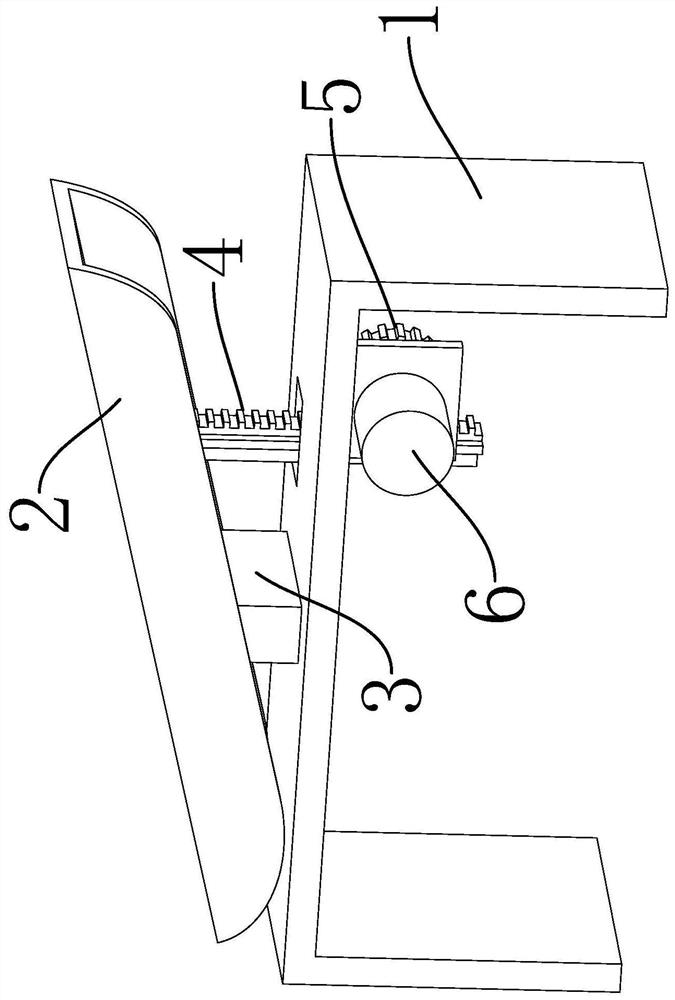
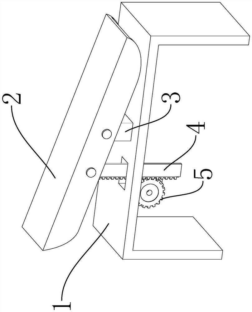
[0005] In addition, during the practical process of the welding machine, the operator often needs to operate with one hand-held welding torch and one hand-held welding wire. The welding current and defecation during the welding process cannot be accurately controlled, and the operator can only use the button on the welding machine before welding Fixed adjustments, making welding less precise

Method used


Image

  • IGBT (Insulated Gate Bipolar Translator) inverted pedal type welding machine control circuit
  • IGBT (Insulated Gate Bipolar Translator) inverted pedal type welding machine control circuit
  • IGBT (Insulated Gate Bipolar Translator) inverted pedal type welding machine control circuit

Examples


Embodiment Construction

[0039] It should be noted that all directional indications (such as up, down, left, right, front, back...) in the embodiments of the present invention are only used to explain the relationship between the components in a certain posture (as shown in the accompanying drawings). Relative positional relationship, movement conditions, etc., if the specific posture changes, the directional indication will also change accordingly.

[0040] In addition, in the present invention, descriptions such as "first", "second", "one" and so on are used for descriptive purposes only, and should not be understood as indicating or implying their relative importance or implicitly indicating the indicated technical features quantity. Thus, the features defined as "first" and "second" may explicitly or implicitly include at least one of these features. In the description of the present invention, "plurality" means at least two, such as two, three, etc., unless otherwise specifically defined.

[00...


PUM


Abstract

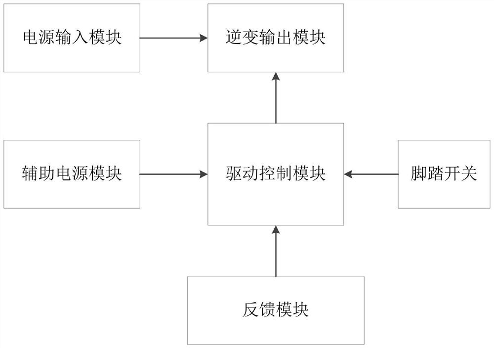
The invention belongs to the technical field of inverter welding machine control, and provides an IGBT (Insulated Gate Bipolar Translator) inverted pedal type welding machine control circuit which comprises a power supply input module; a driving control module; an inversion output module used for performing inversion output on an input voltage obtained through a power supply input module according to a control signal generated by the driving control module to obtain an output current of the welding machine; and a pedal switch which is provided with a potentiometer, wherein the potentiometer is connected with a sixth pin of the driving control module, and the resistance value of the potentiometer is adjusted by stepping on a pedal switch, so that the output current of the welding machine is changed. The pedal type welding machine has the advantages that the pedal type switch is adopted to control the output current of the welding machine, an operator can continuously adjust the output current of the welding machine in the welding process, a better welding effect is achieved, and an SG3525 PWM modulation chip is selected, so that the output current of the welding machine is more accurate.

Description

technical field [0001] The invention relates to the technical field of inverter welding machine control, in particular to an IGBT inverter pedal type welding machine control circuit. Background technique [0002] Welding machine refers to an electrical appliance that provides a certain power supply for welding. Welding is widely used in various industrial fields, such as aerospace, ships, automobiles, containers, etc., due to its advantages of flexibility, simplicity, convenience, firmness and reliability, and even the same strength as the base metal after welding. [0003] At present, in the domestic and foreign markets, the sales volume of welding machines is very large, and they are widely used. However, the quality of the welding machine will be affected by many factors, such as circuit board design, control circuit, manufacturing process, etc. These factors will eventually affect the market competitiveness of the product. [0004] At present, the control circuit design...

Claims


Application Information

Patent Timeline
IPC IPC(8): B23K9/10B23K9/32
CPCB23K9/10B23K9/32Y02P70/10
Inventor 邹磊
Owner NINGBO EUROPA WELDING & CUTTING TECH
Why Eureka
Try Eureka